How to obtain a 4-20ma out of a multivariable modbus flowmeter.

Application Note.
Datexel Product Range
Printed Version

How to obtain a 4-20mA from a Multivariable Modbus flowmeter.

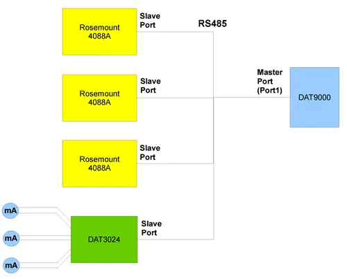
With a Modbus RTU Master and a DAT3024 up to 4 analog outputs can be provided. Add another DAT3024 if you need more 4-20mA outputs and a DAT3130 if you require relay outputs. Another option would be a DAT3011 which would provide 2 analog outputs and 2 relays. Should you require data logging you could swap the DAT9000 and replace it with a DAT9011USB which is able to log the registers and provide 2 x 4-20mA output and 2 relays.
Connect the Flowmeters to the DAT9000 and the DAT3024 as shown below. How to obtain a 4-20mA from a Multivariable Modbus flowmeter

Connect to the DAT9000 using the Application note on how to connect to a DAT9000 using the Dev9K software.

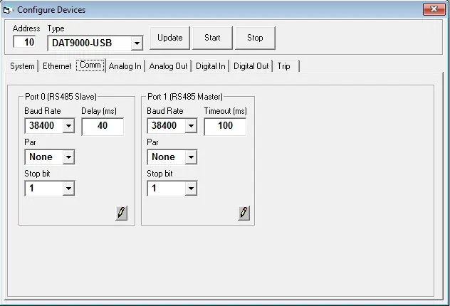
All Modbus devices should have different Addresses and have the same Baud Rate.
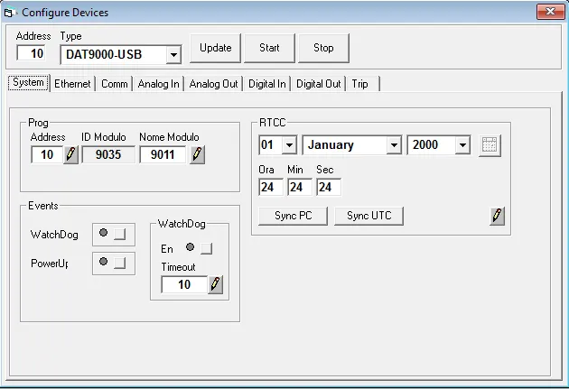
Configure the Communication Parameters of the DAT9000 with the Dev9k software Configuring the Modbus Address on a DAT9000-USB

Configure the DAT9000 Address and click the pencil to write to the device.

Configure the Baud rate on the DAT9000 and click the pencil to write to the device.
Configuring the Modbus Baud Rate on a DAT9000-USB

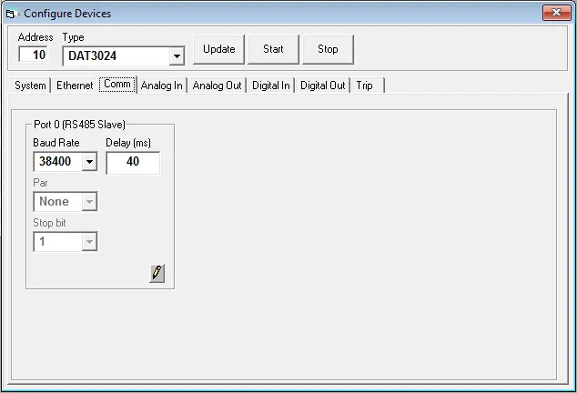
Configure the Communication Parameters of the DAT3024 with the Dev9k software.

Configure the Baud rate on the DAT3024 and click the pencil to write to the device.
Configuring the Baud rate and Address on a DAT3024

Now design a project to read the Multivariable registers and drive the 4-20mA output.

The first 3 blocks are "Read Holding" function blocks. Read the value from the Rosmount multivariable pressure transmitter, and then store it in the DAT9000 register.
The "Address" is the Address of the pressure transmitter.
The "Register" is the place where the data is stored on the pressure transmitter.
The "Number" is 2 for floating number and 1 is for an integer number.
The "Dest" is where the number is stored on the DAT9000.
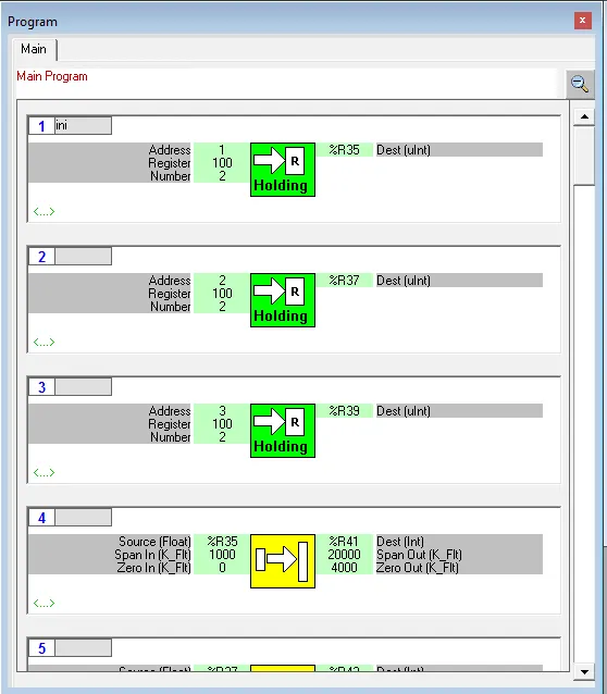
Modbus Program to obtain the pressure from a Multivarible pressure transmitter

Config the time and date in the Modbus Master.

The blocks 4 to 6 "scale" the input to the output and move the value from register %R35 to %R41.
Zero input 0 equal 4000 and span input 1000 equals 20000
"Source" The register to be scaled
"Span in" The high range of the input scale.
"Zero in" The low range of the input scale.
"Dest" The register the data is placed after the scaling.
"Span Out" The span of the analog output.
"Zero Out" The Zero of the analog output.

The block 7 "Write Device" Write to the analog output of the DAT3024 on channels 0 to 2 (Out0, Out1, Out2)
Device DAT3024
Address 4
Resource Analog Out
From 0
To 2
Source The first of the register in the DAT9000

The blocks 8 "Go to" Go to the beginning of the program with the label "ini".
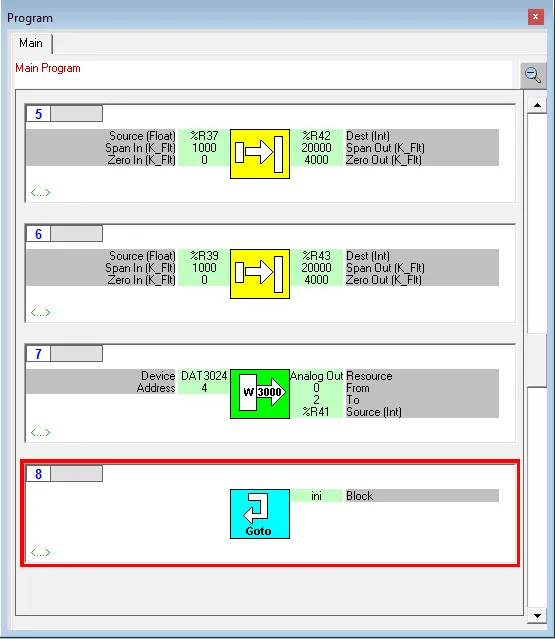
Writing a Modbus Program on a DAT9000 to provide a 4-20mA output