CANopen CAN bus Slave Device Digital Inputs.
DAT7148


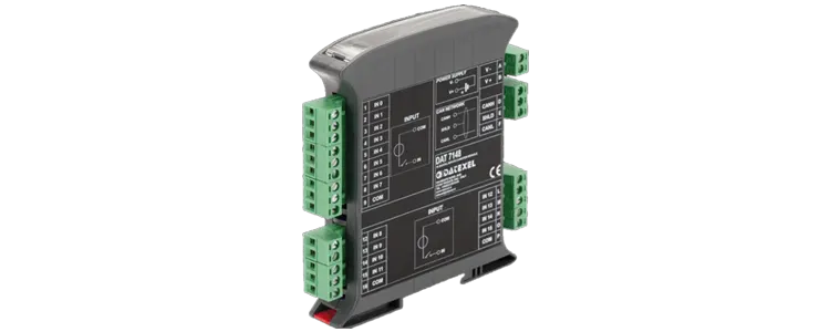
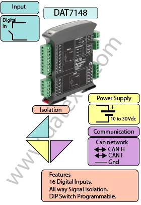
The DAT7148 accepts up to 16 digital inputs. Input states are converted into 16-bit digital data and transmitted over the CANopen (CAN bus) protocol for accurate and reliable integration into distributed automation networks.
The module is fully compliant with CiA DS 301 and CiA DS 401, ensuring interoperability with CAN controllers and devices that follow these standards. This makes the DAT7148 ideal for large-scale digital signal acquisition in industrial automation systems.
Both baud rate and node ID are configured using DIP switches located on the side of the compact 22.5 mm DIN rail mountable enclosure. Plug-in terminals simplify wiring and allow the device to be hot swapped without rewiring. For robust operation, the DAT7148 provides galvanic isolation up to 2000 Vac for 1 minute between inputs, the CANopen network, and the power supply.
| INPUT | OUTPUT | POWER SUPPLY |
|---|---|---|
| 16 Digital Inputs. | CANopen. | Power Supply Voltage 10-30Vdc |
| Reverse polarity protection 60Vdc | ||
| CURRENT CONSUMPTION | CONFIGURATION | ISOLATION |
| Between 60 and 115 mA | PC Programmable | Between Input/Comms/Power Supply 2000Vac. |
| EMC | HOUSING | TEMPERATURE |
| For Industrial environments | Material self-extinguishing | Operating Temperature -4°F +140°F -20°C +60°C |
| Immunity EN 61000-6-2 | Dimensions W x H x T 3 1/2" x 4 1/2" x 7/8" | Storage Temperature -40°F +185°F-40°C +85°C |
| Emission EN 6100-6-4 | 90 x 112 x 22.5 mm | Humidity (non condensing) 0-90% |
| Weight 3 oz 90 g |
| Input: | 16 Channels |
| Off State | Below 3 Vdc |
| On State | Between 10 and 30Vdc |
| Power Supply: | 10 to 30 Vdc. Reverse polarity protection 60 Vdc. |
| Current Consumption: | Current output 35 mA max. Voltage output 25 mA max. |
| Temperature rating: | Operative -4°F +158°F -20°C +70°C |
| Temperature Storage Temperature -40°F +185°F -40°C +85°C. | |
| Humidity: | (non condensing) 0-90%. |
| Housing: | Material self-extinguishing. |
| Dimensions: | 4" x 4 1/2 " x 1", 100 x 120x x 22.5 mm. |
| Weight: | 3 oz 90 g. |
| EMC. | For industrial environments. |
| Immunity: EN 61000-6-2. | |
| Emission: EN 61000-6-4. | |
| Configuration: | PC Configurable and DIP Switch Configurable |
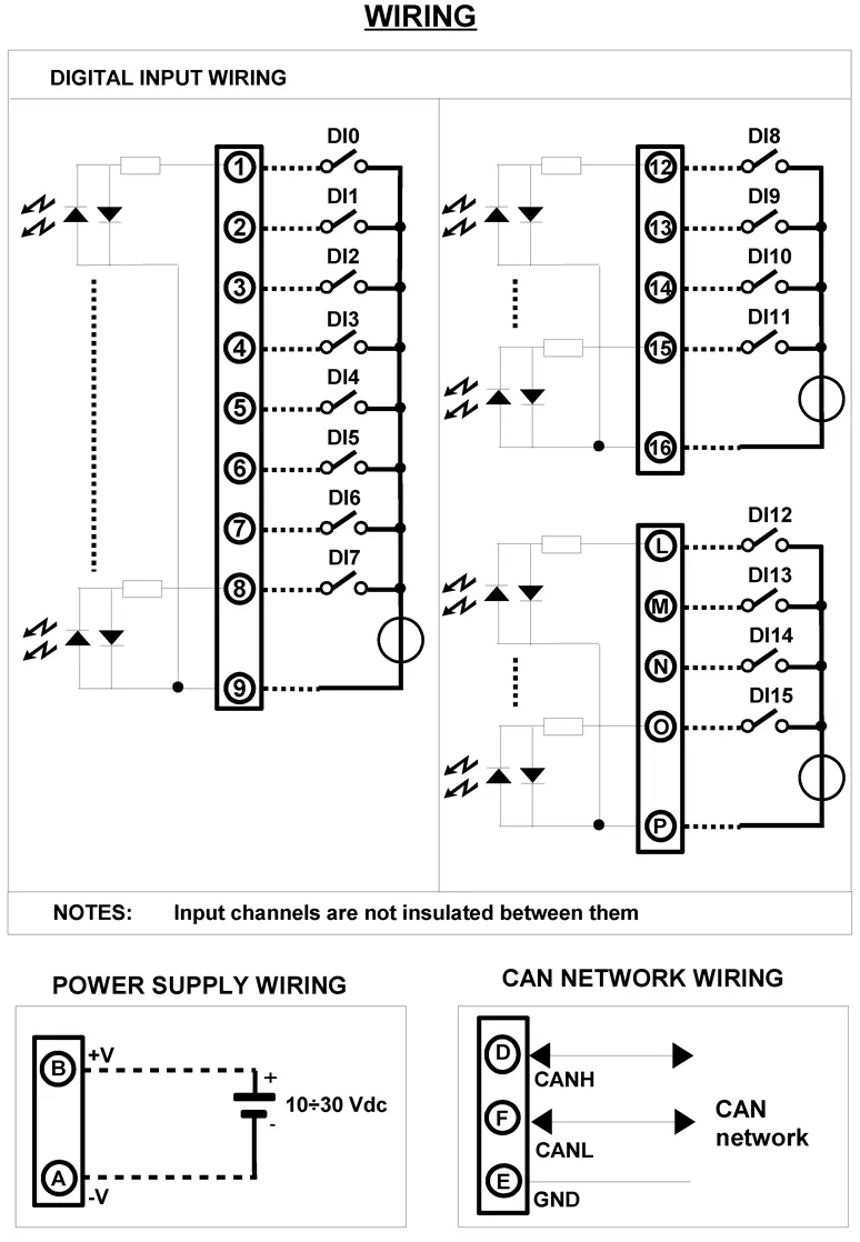
| Input | |
| D 0 | Terminal 9 and 1 |
| D 1 | Terminal 9 and 2 |
| D 2 | Terminal 9 and 3 |
| D 3 | Terminal 9 and 4 |
| D 4 | Terminal 9 and 5 |
| D 5 | Terminal 9 and 6 |
| D 6 | Terminal 9 and 7 |
| D 7 | Terminal 9 and 8 |
| D 8 | Terminal 16 and 12 |
| D 9 | Terminal 16 and 13 |
| D 10 | Terminal 16 and 14 |
| D 11 | Terminal 16 and 15 |
| D 12 | Terminal P and L |
| D 13 | Terminal P and M |
| D 14 | Terminal P and N |
| D 15 | Terminal P and O |
| CAN Network | Terminal D and F Ground E |
| Power Supply | Positive B Negative A |
