RTD Head Mounted Temperature Transmitter.
DAT1010
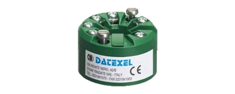

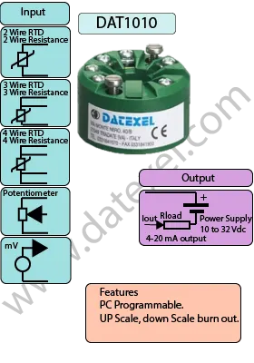
The DAT1010 RTD Temperature Transmitter is an economical, RTD head-mounted Temperature Transmitter solution often referred to as a "hockey puck" transmitter. The DAT1010 is a versatile device that accepts inputs from RTDs, mV, resistance, and potentiometers. The DAT1010 converts these signals into a standardized output of 4-20mA.
The sensor connects to the input terminals, and the signal is processed through a high-impedance measuring circuit. The DAT1010 linearizes the signal and converts it to the industry-standard 4-20mA output.
The DAT1010 RTD Temperature Transmitter is ideal for those needing a reliable, low-cost temperature measurement solution. Its head-mount design saves space and simplifies installation, making it perfect for various industrial applications.
For more information and to purchase the DAT1010 RTD Temperature Transmitter, visit DATEXEL.
| INPUT | OUTPUT | POWER SUPPLY |
|---|---|---|
| RTD Pt100, Pt1000, Ni100, Ni1000. Resistance 0-200 0-500 0-2kΩ | 4-20 mA | Power Supply Voltage 10-30Vdc |
| mV -100 to 700 mV Potentiometer up to 2 k Ω | Reverse polarity protection 60Vdc | |
| CURRENT CONSUMPTION | CONFIGURATION | ISOLATION |
| Between 20 mA | PC Programmable | None Please See DAT1061 |
| EMC | HOUSING | TEMPERATURE |
| For Industrial environments | Material self-extinguishing | Operating Temperature -40°F +185°F -40°C +85°C |
| Immunity EN 61000-6-2 | Dimensions W x H 4 3/4" x 1" | Storage Temperature -40°F +185°F -40°C +85°C |
| Emission EN 6100-6-4 | 43 x 24 mm | Humidity (non condensing) 0-90% |
| Weight 1 1/2 oz 50 g |
| Input type: | Min | Max | Min. span |
| RTD 2,3,4 wires | |||
| Pt100 | -328℉ | 1562℉ | 122℉ |
| -200℃ | 850℃ | 50℃ | |
| Pt1000 | -328℉ | 392℉ | 122℉ |
| -200℃ | 200℃ | 50℃ | |
| Ni100 | -76℉ | 356℉ | 122℉ |
| -60℃ | 180℃ | 50℃ | |
| Ni1000 | -76℉ | 302℉ | 122℉ |
| -60℃ | 150℃ | 50℃ | |
| Voltage | |||
| mV | -100mV | 700mV | 2 mV |
| Potentiometer | |||
| Nominal value | 0Ω | 300Ω | 10% |
| 200Ω | 500Ω | 10% | |
| 0.5KΩ | 50KΩ | 10% | |
| RES. 2,3,4 wires | |||
| Low | 0Ω | 300Ω | 10Ω |
| High | 0Ω | 2000Ω | 10Ω |
| Output type | Min | Max | Min. span |
| Direct current | 4 mA | 20 mA | 4 mA |
| Direct current | 20 mA | 4 mA | 4 mA |
| Input calibration | |
| RTD | > of ±0.1% f.s. or ±3.6 ℉ ±2 ℃ |
| Low res. | > of ±0.1% f.s. or ±0.27 ℉ ±0.15℃ |
| High res. | > of ±0.2% f.s. or ±1 Ω |
| Low res. | > of ±0.1% f.s. or ±3.6 ℉±0.2℃ |
| mV | > of ±0.1% f.s. or ±18 uV |
| Output Calibration | |
| Current | ±7 uV |
| Input impedance | |
| mV | <=10MΩ |
| Linearity (1) | |
| RTD | ± 0.1 % f.s. |
| Line resistance influence | |
| mV | <=0.8uV/Ω |
| RTD 3 wires | 0.05%/Ω 50Ω (balanced max) |
| RTD 4 wires | 0.005%/Ω 100Ω (balanced max) |
| RTD excitation influence | |
| Typical | 0.35mA |
| Thermal drift (1) | |
| Full scale | ±0.018 ℉ ±0.01% ℃ |
| Burn-out values | |
| Max | Output value 20.5mA |
| Min | Output value 3.8mA |
| Max | Fault value 21.6mA |
| Min | Fault value 3.5mA |
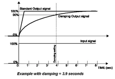
| Damping time constant | |
| Selectable | from 0.3 to 30 s. |
| Value 0 | function not active. |
| Response time (10÷ 90%) | about400 ms |
| Power supply | |
| Power supply voltage | 10 .. 32 Vdc |
| Reverse polarity protection | 60 Vdc max |
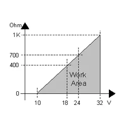
| Load characteristic | Rload (maximum load value on current loop per power supply value) |
| Temperature & humidity | |
| Operative temperature | -40℉ to 185℉ |
| -40℃ to 85℃ | |
| Storage temperature | -40℉ to 185℉ |
| -40℃ to 85℃ | |
| Humidity (not condensed) | 0 to 90 % |
| Housing | |
| Material | PC + ABS V0 |
| Mounting | DIN B head or bigger |
| Weight | 1.76 Oz |
| 50 g. | |
| Dimensions | Dia 1.69" H 0.95" |
| Dia 43mm H 24mm | |
| EMC | for industrial environments |
| Immunity | EN 61000-6-2 |
| Emission | EN 61000-6-4 |
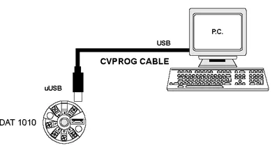
Before programming, ensure that the drivers have been installed on the personal computer.
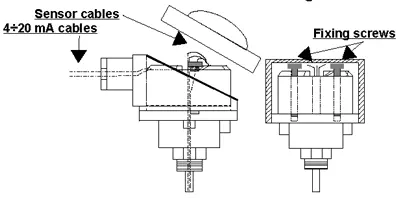
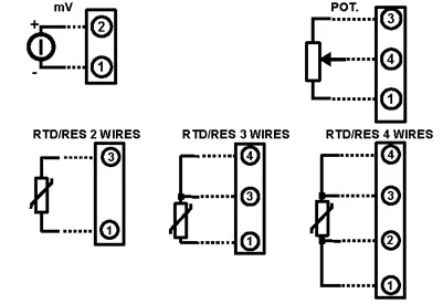
| Input | |
| mV | Positive 2 Negative 1 |
| RTD and Resistance 2 wires | Terminals 1 and 3 |
| RTD and Resistance 3 wires | Terminal 1 and 3 Common 4 |
| RTD and Resistance 4 wires | Terminal 1 Comp 2 and Terminal 3 Comp 4 |
| Potentiometer | Terminal 1 and 3 Wiper 4 |
| Output and Power supply | Positive +V Negative -V |
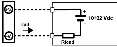
The Impedance is determined by the voltage supplied to the power supply. At 32 Vdc the impedance is 1000Ω at 24 Vdc the Impedance is 700Ω and at around 18 Vdc the Impedance is 400Ω
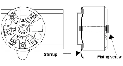
The Diameter is 1.69" and thickness is 0.95". The hole for inserting the thermocouple is 0.28". The center to center for the locating screws is 1.3" apart. To connect the programmer, remove the plastic cap.

We provide the DAT1010 as requested in the customer's order. Refer to the "Technical Specification" section to determine input and output ranges. We include the DIN rail mounting kit only upon request with the code DIN RAIL. You must set the parameters if they are not preconfigured.
| DAT1010 | Pt100 | 3 Wires | 0-200℉ | S.L. | 4-20mA | Burn-out up |
| Column 1 Product Name | DATxxxx |
| Column 2 Input type | RTD, Resistance, mV, or Pot |
| Column 3 Sensor option | RTD/Res 2, 3, or 4 wire |
| Column 4 Input range | Zero and span setting |
| Column 5 linearization | linearization options |
| S.L. Standard linearization | |
| N.L. No linearization | |
| C.L. linearization by step Custom: specify input curve | |
| Column 6 Burn out up | Burnt output option High or Lo |