Modbus Data Logger.

DAT9011DL
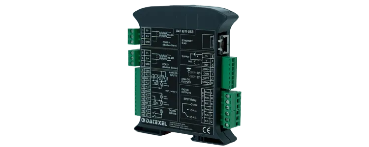
Modbus Data Logger DAT9011DL
Buy Online
Modbus Data logger.
• Modbus Data Logger.
• DAT9011USB Thumb Drive Slot.
• DAT9011DL SD RAM.
• 1 Universal Input T/C's, RTD's, mA, Volts, Pot, Resistance.
• 1 Analog 4-20mA, 0-10Volts Input.
• 2 x Analog 4-20mA Outputs.
• 2 Digital Inputs.
• 2 SPDT Relay Outputs.
• Modbus RS485 Master/Slave.
• Modbus Ethernet 10 Base-T Modbus TCP.
General Description

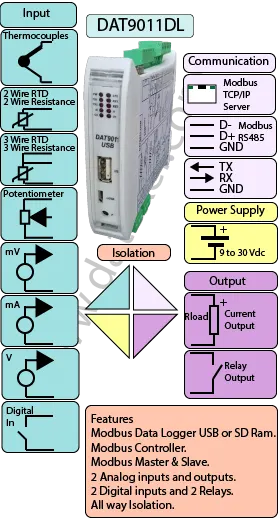
The DAT9011DL and DAT9011USB are Modbus data-logging and data-acquisition controllers that can store selected registers from a Modbus network as well as internal channels. The DAT9011DL logs to an SD memory card, while the DAT9011USB logs to a USB flash drive.

Both variants include on-board I/O: universal analog inputs (Thermocouple, mA, Volts, mV, RTDs, Resistance, Potentiometer), two 4–20 mA analog outputs, two digital inputs (up to 300 Hz), and two relay outputs for alarms/interlocks.

Communication options include RS485 (Modbus RTU) and Ethernet (Modbus TCP), with support for Master or Slave operation. Using Datexel’s free DEV9K software, you can map registers, configure logging (by time schedule and/or register trigger—including using a digital input as a start/stop), and apply processing such as linearization, scaling, averaging, square-root, comparisons, moves/shifts, trips, alarms, and timers.

Logged data can be retrieved by removing the SD/USB media for analysis on a PC or via the Ethernet port without interrupting operation. These loggers can be used alongside other Datexel devices, such as the DAT9550 remote display and the DAT3000 series analog/digital I/O modules. See the Downloads page for application notes, user guides, and the free DEV9K tool.

INPUT OUTPUT POWER SUPPLY
mV, Volts, RTD, Resistance, Potentiometer, mA, Thermocouples. Digital Input. Current 4-20mA, 0-20mA. 2 Relays. Power Supply Voltage 10-30Vdc
Modbus Master/Slave RS485 Modbus TCP Ethernet 10/100T Reverse polarity protection 60Vdc
Modbus TCP Ethernet 10/100T Modbus Master/Slave RS485
CURRENT CONSUMPTION CONFIGURATION ISOLATION
Between 45 and 170 mA PC Programmable Between Input/Comms/Power Supply 1500Vac.
EMC HOUSING TEMPERATURE
For Industrial environments Material self-extinguishing Operating Temperature 14°F +140°F -10°C +60°C
Immunity EN 61000-6-2 Dimensions W x H x T 4" x 4 3/4 " x 7/8 " Storage Temperature -40°F +185°F-40°C +85°C
Emission EN 6100-6-4 100 x 120x x 22.5 mm Humidity (non condensing) 0-90%
Weight 3 oz 90 g

Specifications
Input  
Analog Input  
Channel 0: mV -100 to 100mV, Volts -100mV to 10V, Current 4-20mA, 0-20mA. RTD Pt100, Pt 1000, Ni100, Ni1000. Resistance 0-2000, Ohm. Potentiometer 20-2000 Ohm. Thermocouple J,K,R,S,B,E,T, N.
Channel 1: mV -100 to 100mV. Volts -100mV to 10V. Current 4-20mA, 0-20mA.
Digital Input 4 Channels.
Threshold 0-3 Volts Off, 10-30V On.
Frequency 300 Hz Maximum.
Output  
Analog  
Channel 1 and 2 Current 4-20mA.
Digital
Channel 1 and 2 2 Relays SPDT 2 Amp at 250 V.
Communication:  
RS485: Port 1 Modbus RTU Master, Port 0 Modbus RTU Slave.
Ethernet: Ethernet 10Base-T, Modbus TCP.
Power Supply: Voltage 10 - 30 Vdc. Reverse polarity protection 60 Vdc.
Current Consumption: 80 mA max.
Temperature rating: Operative Temperature - 4°F +140°F -20°C +60°C Storage Temperature - 40°F +185°F -40°C +85°C.
Humidity: (none condensing) 0-90%.
Housing: Material self-extinguishing.
Dimensions: W x L x H 4 x 4 3/4 x 1inch, 100 x 120 x 22.5mm.
Weight: 7 oz 200 g.
EMC. For industrial environments.
Immunity: EN 61000-6-2.
Emission: EN 61000-6-4.
Isolation: 1500Vac, 50Hz, 1 minute.
Configuration: PC Configurable with Ethernet.
Drawings

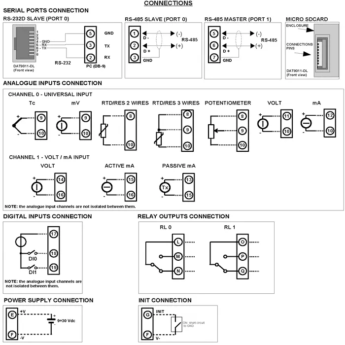
DAT9000DLIO Wiring Diagram

Input. Channel 0 Channel 1
Analog    
Thermocouple Positive 9 Negative 10 N/A
mV Positive 9 Negative 10 N/A
RTD and Resistance 2 Wire 8 and 10 N/A
RTD 3 Wire 8 and 10 Compensation 9 N/A
Potentiometer 8 and 10 Wiper 9 N/A
Volts Positive 11 Negative 10 Positive 14 Negative 16
mA Positive 12 Negative 10 N/A
mA Active N/A Positive 15 Negative 16
mA Passive N/A Positive 13 Negative 15
Digital    
DI0 17 and 18  
DI1 17 and 19  
Output Analog    
Current Positive I Negative H Positive J Negative H
Output Digital    
Relay Common L, NO M, NC N. Common O, NO P, NC Q.
Power Supply (18-30Vdc). Positive E Negative F.  
Modbus Data Logger wiring Diagram.
Applications
Frequently Asked Questions
Back to General Description
Application Note, Data Logging Registers from Current Transformers.
This application reads the Current registers in several Current Transformers Model QEED QI-50-V-485 with a DAT9011DL USB and then saves the reading to a USB Thumb Drive.
Printed Version

Start-up.

  1. The Modbus Slave Current Transformers are set up to Baud Rate 38400, Parity None and 1 Stop bit.
  2. The CT’s are set to Address 1, 2 and 3. The DAT9011DL USB Modbus Master is set to Address 10.
  3. Connect to the DAT9011DL with the Ethernet Port. This method is shown on Ethernet Connection Application Note found on the Datexel download page.
  4. This application note starts where you have set the DAT9011DL as the Controller and Clicked the Yellow Box with R in it and read the default Registers.
Reads the Current registers in CT QEED QI-50-V-485 with DAT9011DL then saves to a USB Thumb Drive.

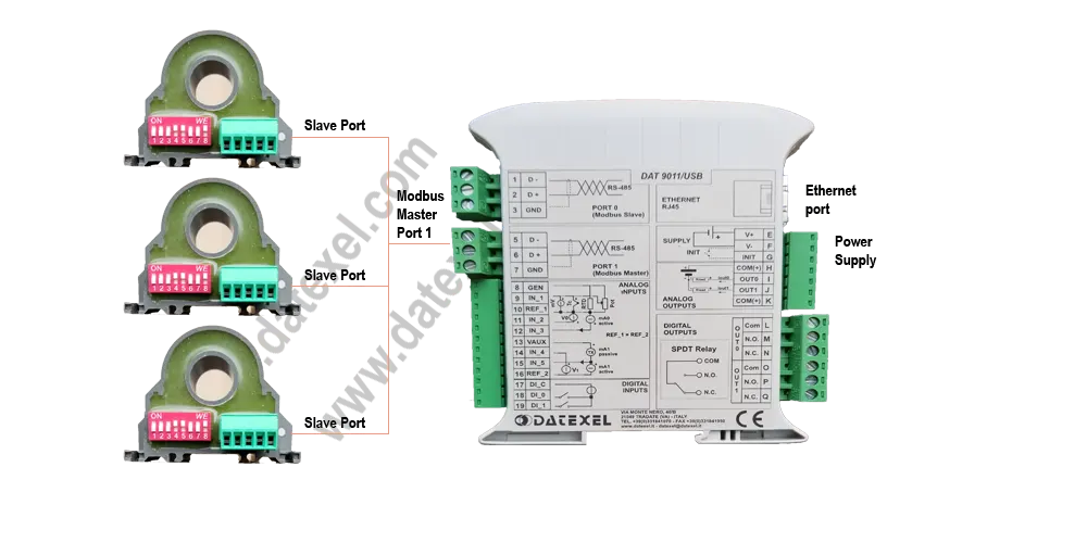
Wiring connections for Modbus Current Transformers and the Data logger.

  1. Wire the CT’s to the Master port on the DAT9011DL.
  2. Connect 24 Vdc power supply to the CT’s and the Data Logger.
  3. Run the Dev9K software from Datexel download page.
Only after communicating with the DAT9011DL can you configure the Modbus Master port to communicate with the Current Transformers.

Configure the Modbus Master Port.

The devices will not communicate to each other unless they have the same Baud rate, Parity, and Stop bit.
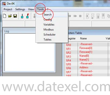
  1. Click on Tools.
  2. From the drop down menu click Config.
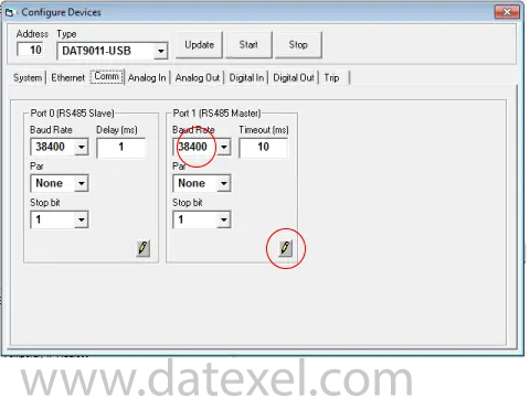
Setting up Modbus Datalogger comm port.

Setting up Modbus Master Buad Rate.

  1. Click on Comm.
  2. The Baud Rate on Port 1 (RS485 Master) must be the same as the CT’s 38400. Change the communication settings on the Modbus Master Port 1.
  3. Finally click update.
  4. It is a good idea to close the box and open again to check that the comm port changes have been uploaded to the DAT9011DL. From the drop down menu click Config.
Setting up Modbus Master Datalogger Buad Rate.

Now you are ready to write the Data logger program.

  1. Click the Project label at the top.
  2. Click New in the Drop down menu.
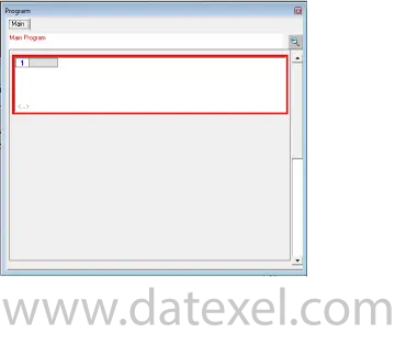
  3. The Program outline should open.
Program to the DAT9011DL USB

Insert Function Blocks.

The program is made up with a group of function blocks. More information on these function blocks are available in the DAT9xxx user guide. Importantly the first function block must be labeled start and the last function block must be a goto function block with the command return to start. You can insert a function block anywhere in the program with the Insert Before or Insert After label.
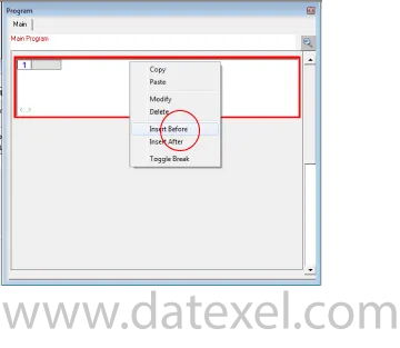
Insert Function Blocks.

Reading the Current reading from the CT’s.

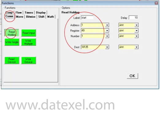
It is advisable to set up the data logger in steps. This step is to read the Current (Amps) input from a single CT and store it in Register 35 in the DAT9011DL.

  1. Right click on Function Block 1.
  2. On the drop down menu click Modify.
  3. Click Comm and select Read Holding.
  4. Write start in the Label. (Important).
  5. The Address of the CT is 1.
  6. The Register where the Amp reading is stored is Register 49.
  7. We are only reading 1 register from the Current Transformer so enter 1.
  8. The Destination for this Current (Amp) reading is register 35.
  9. Click OK.
  10. It is best now to run this part of the project to make sure you are communicating with the Current Transformer and storing the register in destination register 35.
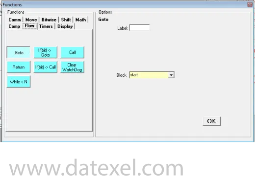
  11. Insert another function block called “Flow”, Click “Goto”. In the Block box wright start. Make sure it is the same case and spelling as the Label in the first function block.
Setting up Modbus Master comm port. Setting up Modbus Datalogger comm port.

Saving the Project.

The project should now have 2 Function Blocks and should be stored to the PC.

  1. Click “Project” on the drop down menu Click “Save as”
  2. Save as reading1ct.
Insert Function Blocks.

Downloading the project from the PC to the DAT9011DL.

  1. Reconnect to the DAT9011DL and set the DAT9011DL to be the controller.
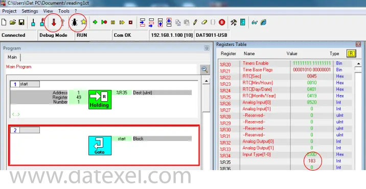
  2. Click the Debug button.
  3. Click the Download button, in the download drop down menu click OK.
  4. The software will now download from the PC to the DAT9011. The yellow LED on the front of the DAT90011DL will now flash slowly.
  5. Wait until the download has finished.
  6. It is very important now to click the Release mode and both the TX2 and RX2 LED’s will flash quickly.
  7. Now the program is stored in the DAT9011DL.
  8. Click the yellow R register button on the register table and check that the reading is in Register 35.
  9. If you have connection and have a reading in 35 then copy function block 1 twice and change the Address to 2 and 3. Make sure you remove the start label in function block 2 and 3 otherwise the loop will only be to function block 3.
  10. Save the project and download and release and you should have readings in 35, 36, and 37.
  11. You may have to reconnect to the DAT9011DL and set as controller again.
Storing Registers in Modbus Datalogger internet memory.

Selecting which Registers to save and format.

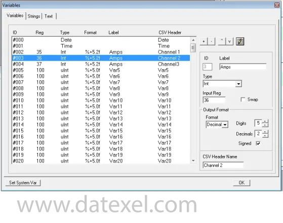
The current readings are in register 35, 36 and 37 and stored without decimal places. The 183 seen in the register 35 is actually 1.83 Amps.

  1. Click “Tool” and open the “Variables” page.
  2. Select the first line enter Date for Label, Click Type and Select Date on the Drop down menu. Type Date in the CSV Header Name.
  3. On the second line enter Time for Label, Type and CSV Header.
  4. The third line is recording the Current (Amps) on Channel 1. Under Label enter Amps, under Type select Int, for Input Reg type 35. The format will be decimal 5 digits with 2 decimal points. Under CVS Header Name type Channel 1.
  5. Repeat Section 4 in the next 2 lines for the other two channels.
  6. Click the pencil to write to the project file.
Selecting which register to store.

Setting the logging period.

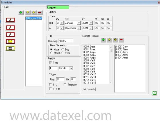
You can choose when to log the stored information. It can be every Minute, Hour or Day. You can also select a trigger from a register to start the logging.

  1. Click “Tool” and open the “Scheduler” page.
  2. Click on the Item to log and click the + sign to move it over to the right side.
  3. Click how often you want to write a new file.
  4. Click the time period to record each log (it cannot be less than 10 seconds).
  5. Click the pencil.
  6. Click the save the project file.
Setting up when to Store the internal Registers.

Run the Project

  1. Set the DAT9011DL as the controller
  2. Set into Debug mode.
  3. Click Release. Important, otherwise the project is not stored in the EEPROM and will be deleted on power reset.
  4. Insert a USB Thumb Drive, wait 10 minutes, remove the Thumb Drive and check you have a CSV file.

Explanation of the Project.

DAT9011USB Custom-Made Products

What is DAT9011USB 40917?
DAT9011USB 40917 adds a debounce timer on the digital inputs to filter contact bounce.
What is DAT9011USB 271017?
DAT9011USB 271017 includes an input channel capable of accepting ± 30 VDC.
What is DAT9011USB 240718?
DAT9011USB 240718 features an input adapted for an EVO flow sensor.
Back to General Description