Choosing Between 4-20mA, RTDs, and Thermocouple Signal Splitters


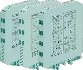
If you add a control room device to a control loop, you’ll likely need to add a signal splitter to the loop. A signal splitter sends the same 4-20mA or voltage to more than one control room device, such as a PLC or recorder. Or maybe you’re adding a process controller to an existing loop.
Another reason you may need a signal splitter is to improve the impedance and spread the load across two or more existing control loops, which provides a much safer installation. Read on to learn more about choosing between 4-20mA, RTD, and thermocouple signal splitters.
If you add a signal splitter to a loop, adding an isolated signal splitter is always advisable. This will provide the same signal on all the control room devices and provide isolation between the input loop and the two output loops.
Most standard outputs are 4-20mA output, but you may need a voltage output such as 0-10V. Some simple splitters convert an input such as 4-20mA to two 4-20mA outputs. Others can convert instrumentation signals such as voltage, thermocouples, RTDs, and mV to current or voltage.
Another advantage of a signal splitter is the cost savings due to the need for less equipment. Instead of having two RTDs and two RTD transmitters, you can just have one RTD and connect it to an RTD signal splitter converter, and that will supply the two 4-20mA outputs. You can repeat this installation with a thermocouple or thermistor.
The signal splitter options available today are current, voltage, resistance, mV, thermocouple, RTD, potentiometers, and thermistors input and current or voltage output. By looping the input, two or more signal splitters can work together so that you can provide 2, 4, 6, or even more 4-20mA output from one input. Low-cost versions are available for current and voltage inputs and outputs.
There’s also the option to have a relay output. On some inputs, the engineer can select passive or active 4-20mA input, and on the output, they can choose passive or active 4-20mA output. Some signal splitters are smart, which allows the customer to configure the inputs and outputs and the limit alarm by software or DIP switches.