Mathematical Signal Conditioner.
DAT4632D


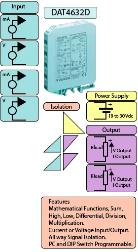
The DAT4632D is a DIN rail mount mathematical signal conditioner that performs real-time operations on two analog inputs and provides two isolated analog outputs. Supported mathematical functions include Sum, Difference, Multiplication, Division, Maximum (High) selector, and Minimum (Low) selector. These functions can be configured independently for each channel using PC software or DIP switches.
The DAT4632D measures current or voltage signals on both input channels, applies a programmable mathematical function, and outputs the computed result as a normalized voltage or current signal. The device offers 1500 Vac galvanic isolation between inputs, outputs, and power supply to ensure robust performance in industrial environments.
Configuration can be performed using DIP switches accessible through a side window or via a PC using the Prodat programming software. All critical parameters can be configured, including input range, output type, and the applied math function (including any constants). Both output channels can be configured to compute separate or identical functions.
Input terminals support active current loops for mA signals. Output options include voltage or current signals, allowing easy integration with PLCs, SCADA systems, or controllers.
The DAT4632D is housed in a compact 12.5 mm-wide plastic case suitable for DIN rail mounting according to EN-50022 and EN-50035 standards. It is powered via terminals Q and R.
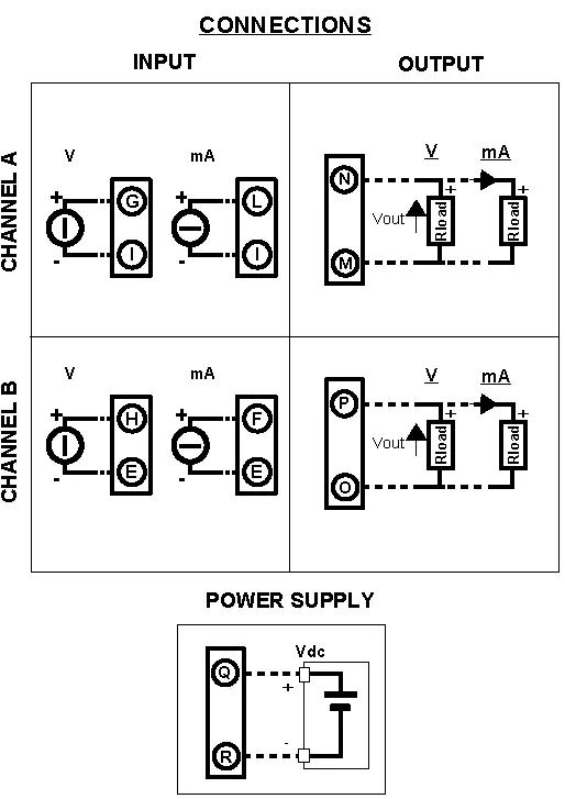
Channel A accepts input via terminals I, L, and G and outputs the signal to terminals N and M. Channel B accepts input via terminals E, F, and H and outputs to terminals P and O. Inputs and outputs must be wired according to the product manual to ensure proper operation.
DIP switch configuration can be done with the device powered. Once configuration changes are made, allow a few seconds for the output to stabilize. For advanced setups and function programming, use the Prodat software with the appropriate PC interface.
| INPUT | OUTPUT | POWER SUPPLY |
|---|---|---|
| Current 4-20mA, 0-20mA. | Current 4-20mA, 0-20mA. | Power Supply Voltage 14-30Vdc |
| Voltage 0-10V Min Span 1 V. | Voltage 0-10V Min Span 1 V. | Reverse polarity protection 60Vdc |
| CURRENT CONSUMPTION | CONFIGURATION | ISOLATION |
| Between 60 and 115 mA | PC Programmable | 3 Way 1500Vac. |
| EMC | HOUSING | TEMPERATURE |
| For Industrial environments | Material self-extinguishing | Operating Temperature -4°F +140°F -20°C +60°C |
| Immunity EN 61000-6-2 | Dimensions W x H x T 3 1/2" x 4 1/2 " x 1/2" | Storage Temperature -40°F +185°F-40°C +85°C |
| Emission EN 6100-6-4 | 90 x 112x x 12.5 mm | Humidity (non condensing) 0-90% |
| Weight 3 oz 90 g |
| Input: | Current 4-20mA, 0-20mA Min span 4mA.
Voltage 0-10V Min Span 1 V. |
| Output: | Current 4-20mA, 0-20mA Min span 4mA. Voltage 0-10V Min Span 1 V. |
| Functions: | |
| =A | A Output = A Input. |
| =B | B Output = B Input. |
| A + B | Output is proportional to the sum between A and B (input). |
| A - B | Output is proportional to the difference between A and B (input). |
| A X B | Output is proportional to the multiplication between A and B (input). |
| A / B | Output is proportional to the division between A and B (input). |
| Max | Output is the higher value of the inputs. |
| Min | Output is the lower value of the inputs. |
| Power Supply: | 18 to 30 Vdc |
| Temperature rating: | Operative -4°F +158°F -20°C +70°C |
| Temperature Storage Temperature -40°F +185°F -40°C +85°C. | |
| Humidity: | (non condensing) 0-90%. |
| Housing: | Material self-extinguishing. |
| Dimensions: | 3 1/2" x 4 1/2 " x 1/2", 90 x 112x x 12.5 mm. |
| Weight: | 3 oz 90 g. |
| EMC. | For industrial environments. |
| Immunity: EN 61000-6-2. | |
| Emission: EN 61000-6-4. | |
| Configuration: | PC |
| Input. | Channel A | Channel B |
| Voltage | Positive G Negative I | Positive H Negative E |
| Current | Positive L Negative I | Positive F Negative E |
| Signal Output. | ||
| Voltage. | Positive N Negative M | Positive P Negative O |
| Current. | Positive N Negative M | Positive P Negative O |
| Power Supply (18-30Vdc). | Positive Q Negative R. |
