Thermocouple to Modbus TCP.
DAT8016
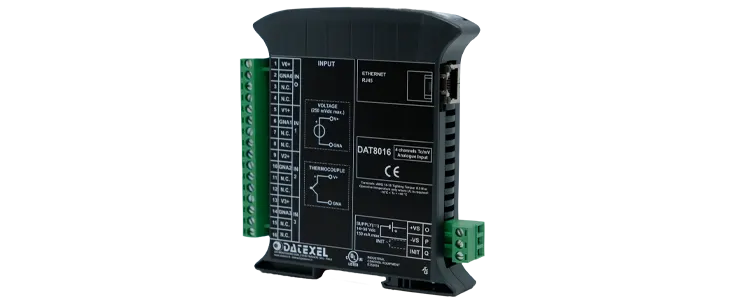

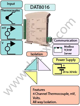
The DAT8016 is a high-performance 4-channel converter that fully isolates Thermocouple and mV inputs and converts them to Modbus TCP over Ethernet 10/100BaseT. Designed for industrial applications, the DAT8016 provides reliable and precise measurements for a variety of processes and equipment monitoring tasks.
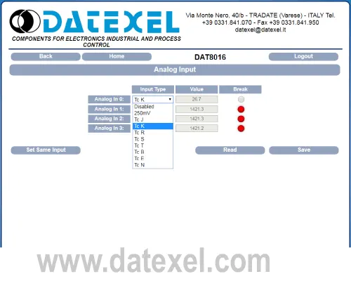
This versatile device can accept inputs from a wide range of thermocouples, including J, K, R, S, B, E, T, and N types, as well as millivolt signals from -250 mV to +250 mV. Each input channel is fully isolated from the Ethernet network and power supply, providing up to 1500 VAC isolation for 1 minute, which ensures safe operation in electrically noisy environments.
The DAT8016 operates with a wide DC power supply range from 10 to 30 Vdc, making it compatible with a variety of industrial control systems. It is conveniently DIN Rail mountable, simplifying installation in control cabinets and panels.
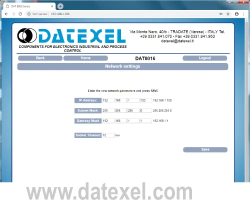
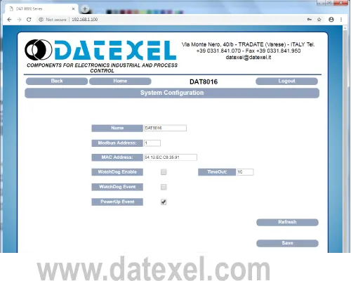
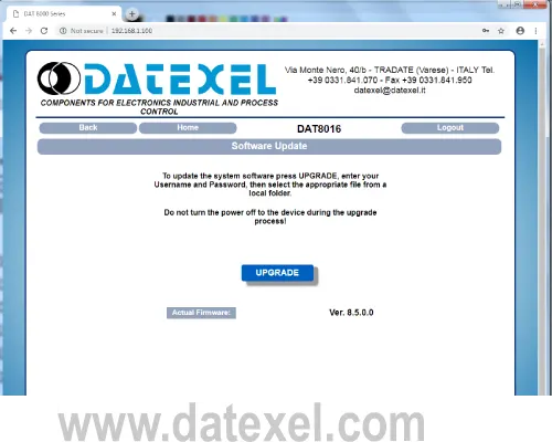
Configuration and monitoring are easy via the Modbus TCP protocol, which allows seamless integration with SCADA systems, PLCs, or data acquisition software. The DAT8016 is ideal for applications requiring accurate temperature or mV signal conversion with full channel isolation, such as process control, laboratory measurement, or industrial automation.
The DAT8016 is an essential solution for anyone looking to convert multiple thermocouple or mV signals into digital data, while maintaining complete electrical isolation and compatibility with modern Ethernet-based control systems.
| INPUT | OUTPUT | POWER SUPPLY |
|---|---|---|
| J, K, R, S, B, E, T, N, Type T/c's 25 to 25 mV. | Modbus TCP Ethernet 10/100T | Power Supply Voltage 14-30Vdc |
| -100 to 100mV. -250 to 250 mV. | Reverse polarity protection 60Vdc | |
| CURRENT CONSUMPTION | CONFIGURATION | ISOLATION |
| Between 60 and 115 mA | PC Programmable | Between Input/Comms/Power Supply 1500Vac. |
| EMC | HOUSING | TEMPERATURE |
| For Industrial environments | Material self-extinguishing | Operating Temperature 14°F +140°F -10°C +60°C |
| Immunity EN 61000-6-2 | Dimensions W x H x T 4" x 4 3/4" x 3/4" | Storage Temperature -40°F +185°F-40°C +85°C |
| Emission EN 6100-6-4 | 100 x 120 x 22.5 mm | Humidity (non condensing) 0-90% |
| Weight 6 oz 160 g |
| Input: | |
| Channels | 4 Channels. |
| Thermocouples | J, K, R, S, B, E, T, and N. |
| mV | -25 to 25 mV, -100 to 100mV, -250 to 250 mV. |
| Communication: | |
| Ethernet 10/100T: | Modbus TCP. |
| Power Supply: | 14 - 30 Vdc. Reverse polarity protection 60 Vdc. |
| Current Consumption: | 60 mA Standby 115 mA Max. |
| Temperature rating: | Operative Temperature 14°F +140°F -10°C +60°C Storage Temperature - 40°F +185°F - 40°C +85°C. |
| Humidity: | (not condensing) 0-90%. |
| Housing: | Material self-extinguishing. |
| Dimensions: | W x H x T 4 3/4 x 4 x 7/8 inch, 120 x 100 x 22,5mm. |
| Weight: | 6 oz 160 g. |
| EMC. | For industrial environments. |
| Immunity: | EN 61000-6-2. |
| Emission: | EN 61000-6-4. |
| Isolation: | Input, Each Channel, Power Supply, 1500Vac, 50Hz, 1 Minute. |
| Configuration: | PC Configurable. |
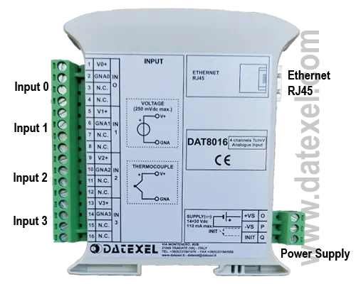
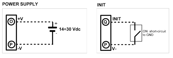
| Power Supply (18-30Vdc). | Positive O Negative P. |
| Init | Pin Q Init Gnd P |
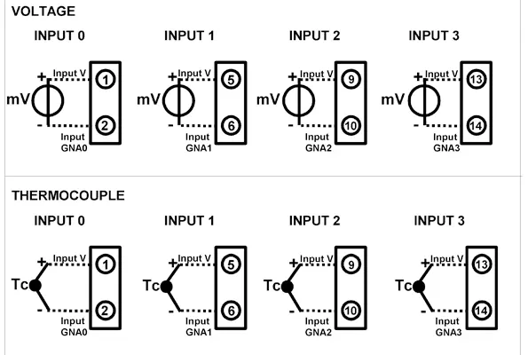
| Voltage Input | |
| Input 0 | Positive 1 Negative 2 |
| Input 1 | Positive 5 Negative 6 |
| Input 2 | Positive 9 Negative 10 |
| Input 3 | Positive 13 Negative 14 |
| Thermocouple Input | |
| Input 0 | Positive 1 Negative 2 |
| Input 1 | Positive 5 Negative 6 |
| Input 2 | Positive 9 Negative 10 |
| Input 3 | Positive 13 Negative 14 |
