Modbus Data Logger with Digital IO
DAT9000DLIO
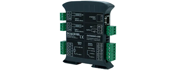

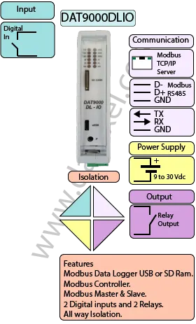
The DAT9000DLIO is a data acquisition and logging controller with an integrated microSD slot for on-board data logging. In addition to its logging capability, it provides 4 digital inputs and 2 relay outputs for alarms, interlocks, and simple control tasks.
Like the DAT9000DL, the DAT9000DLIO can operate as a Modbus RTU Master or Slave and includes RS485 and Ethernet (Modbus TCP) ports. It can poll and control a network of slaves, read/write registers, and execute logical and mathematical functions such as linearization, scaling, averaging, and square-root extraction.
Logged data can be saved from internal or polled registers to the microSD card for later analysis, either by removing the card or accessing the files via Ethernet. Configuration is performed with Datexel’s DEV9K software (free of charge), which streamlines register mapping, processing rules, logging triggers, and communication settings.
| INPUT | OUTPUT | POWER SUPPLY |
|---|---|---|
| 4 Digital Inputs | 2 Relays SPDT | Power Supply Voltage 18-30Vdc |
| Modbus Master/Slave RS485 | Modbus TCP Ethernet 10/100T | Reverse polarity protection 60Vdc |
| Modbus TCP Ethernet 10/100T | Modbus Master/Slave RS485 | |
| CURRENT CONSUMPTION | CONFIGURATION | ISOLATION |
| Between 45 and 80 mA | PC Programmable | Between Input/Comms/Power Supply 1500Vac. |
| EMC | HOUSING | TEMPERATURE |
| For Industrial environments | Material self-extinguishing | Operating Temperature 14°F +140°F -10°C +60°C |
| Immunity EN 61000-6-2 | Dimensions W x H x T 4" x 4 3/4 " x 7/8 " | Storage Temperature -40°F +185°F-40°C +85°C |
| Emission EN 6100-6-4 | 100 x 120x x 22.5 mm | Humidity (non condensing) 0-90% |
| Weight 7 oz 200 g |
| Input | 4 Channels. |
| Threshold | 0-3 Volts OFF 10-30V On. |
| Frequency | 300 Hz Maximum. |
| Output | 2 Relays SPDT 2 Amp at 250 V. |
| Data Logging: | 1 Micro SD Card |
| Communication: | |
| RS485: | Port 1 Modbus RTU Master, Port 0 Modbus RTU Slave. |
| Ethernet: | Ethernet 10Base-T, Modbus TCP. |
| Power Supply: | Voltage 10 - 30 Vdc. Reverse polarity protection 60 Vdc. |
| Current Consumption: | 80 mA max. |
| Temperature rating: | Operative Temperature -4°F +140°F -20°C +60°C Storage Temperature -40°F +185°F -40°C +85°C. |
| Humidity: | (none condensing) 0-90%. |
| Housing: | Material self-extinguishing. |
| Dimensions: | W x L x H 4 x 4 3/4 x 1inch, 100 x 120 x 22.5mm. |
| Weight: | 7 oz 200 g. |
| EMC. | For industrial environments. |
| Immunity: | EN 61000-6-2. |
| Emission: | EN 61000-6-4. |
| Isolation: | 1500Vac, 50Hz, 1 Minute. |
| Configuration: | PC Configurable, DIP Switches. |
| RS-485 | Slave | Master |
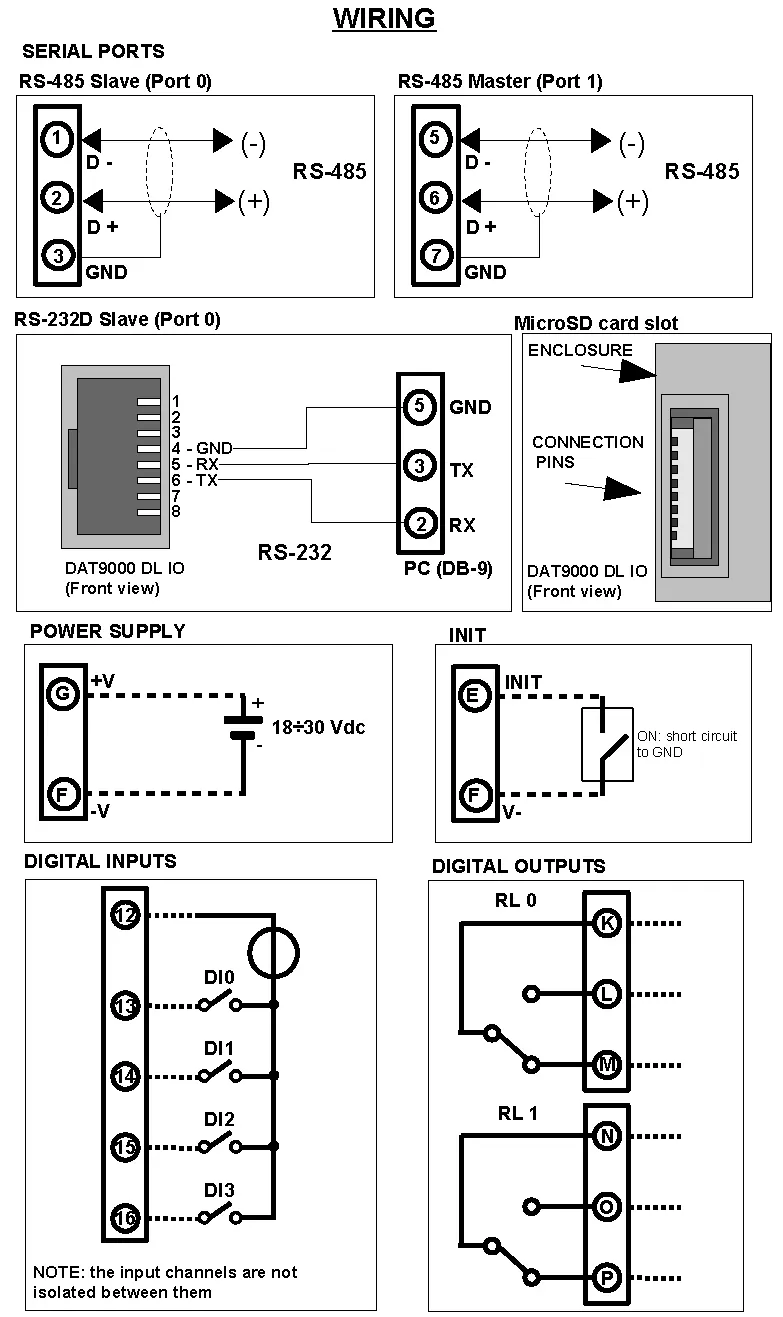
| D- | Port 0 Pin 1 | Port 1 Pin 5 |
| D+ | Port 0 Pin 2 | Port 1 Pin 6 |
| GND | Port 0 GND | Port 1 GND |
| RS-232D | Front view | PC DB9 |
| GND | Port 0 Pin 4 | Pin 5 |
| RX | Port 0 Pin 5 | Pin 3 |
| TX | Port 0 Pin 6 | Pin 2 |
| Power Supply (18-30Vdc). | Positive G Negative F. | |
| INIT | Short pin E to F | |
| Digital Input | Common | Input |
| DI0 | Pin 12 | Pin 13 |
| DI1 | Pin 12 | Pin 14 |
| DI2 | Pin 12 | Pin 15 |
| DI3 | Pin 12 | Pin 16 |
| Relay 0 | K | NO L NC M |
| Relay 1 | N | NO O NC P |
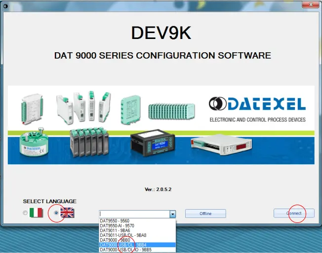
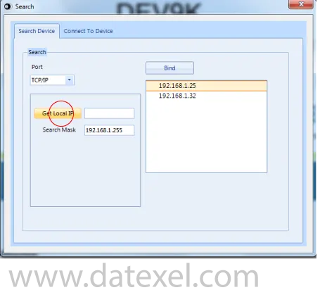
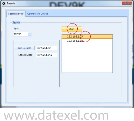

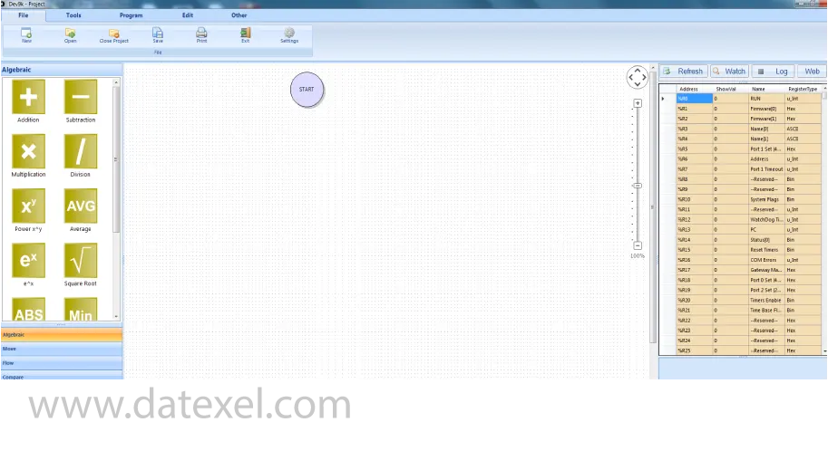
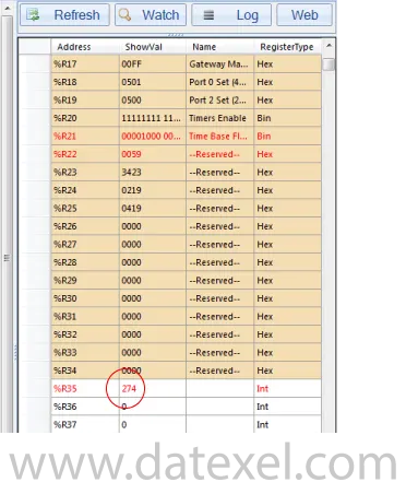
This is the main control screen for the Dev 9k Version 2. From here you can configure the Communication ports. Design and save new projects and open existing projects. In the left panel you have the function blocks. The center is the layout page for the program with the START position. On the right panel you have the registers. By Clicking the Refresh you can see what is stored in the registers.
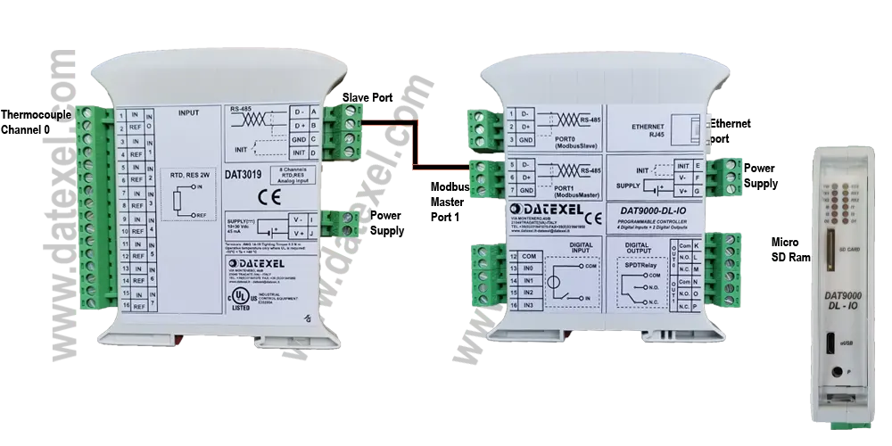
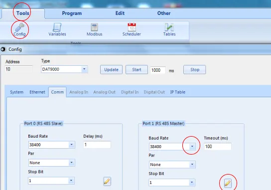
The DAT3019 and the DAT9000DL Modbus Controller need to have the same communication settings. The Master control port (1) on the DAT9000DL needs to be set up.
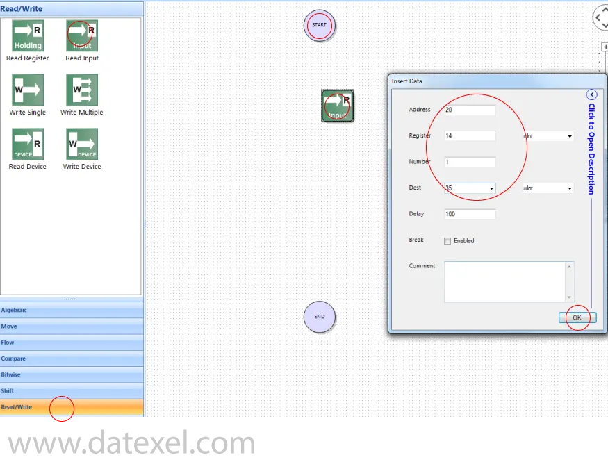
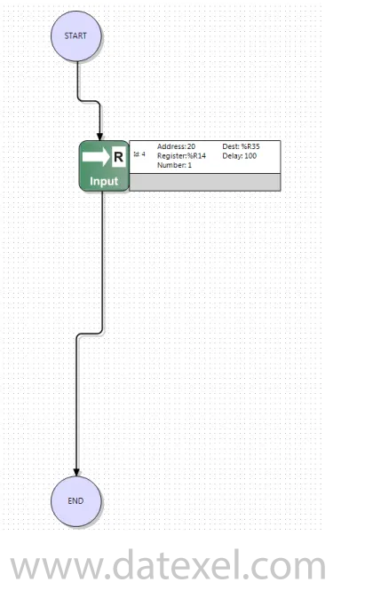
There is only 1 Function block in the program. The Function Block will read register 40015 which is Channel 0 on the DAT3019 and the Address of the DAT3019 is 20. The Function block will poll the DAT3019 and obtain the Integer and place it into the DAT9000DL on register 35. We will be using a Read Input and must deduct 40001 from the register table so the actual Register we use on the read Input Function Block will be 14.
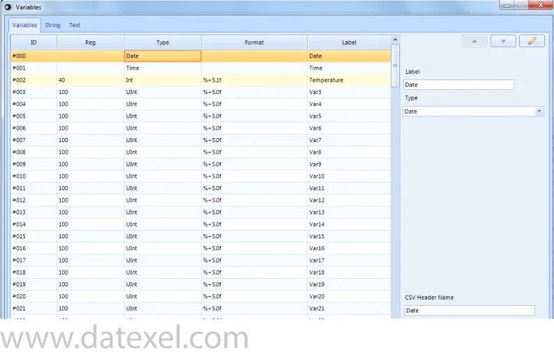
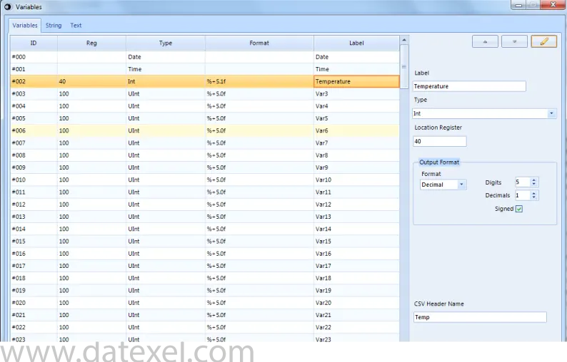
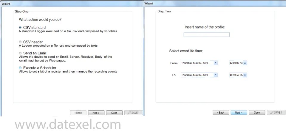
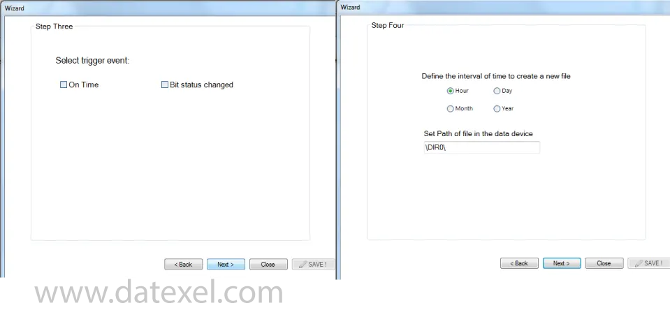
The DAT9000DLIO is a data acquisition and logging controller with an integrated microSD slot for on-board data logging. It adds 4 digital inputs and 2 relay outputs for alarms, interlocks, and simple control tasks, while supporting Modbus RTU (RS485) and Modbus TCP (Ethernet).
The DAT9000DLIO includes digital I/O (4 digital inputs and 2 relay outputs) in addition to the logging features found on the DAT9000DL. Communications and processing capabilities remain the same.
It provides 4 digital inputs and 2 relay outputs. Refer to the user manual for electrical ratings, wiring types, and isolation details before connecting field devices.
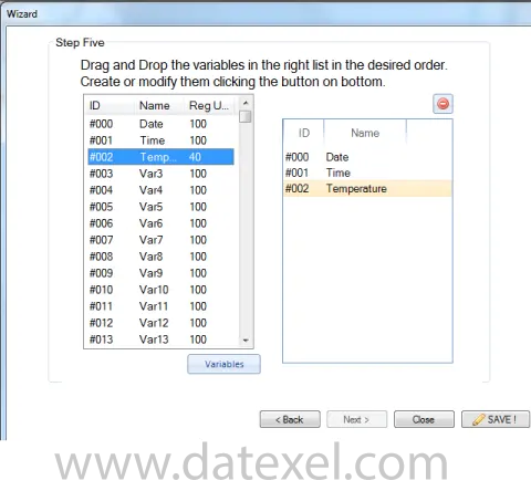
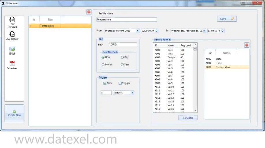
Configuration is done with Datexel’s DEV9K software (free of charge). You can define Modbus maps, set logging rules, map digital inputs/relay outputs, and configure communication parameters for Modbus RTU and Modbus TCP.
You can flag a register to start logging or set a time-based schedule/interval. In DEV9K, you may also map a digital input as a trigger to begin or halt logging based on external events.
Remove the microSD card for analysis on a PC, or use the Ethernet port to retrieve saved files without interrupting operation.
Yes. It can poll Modbus RTU devices on RS485 and expose selected data to Modbus TCP clients over Ethernet, or mirror specific registers between the two buses depending on configuration.
Pair the controller with a Modbus output module such as the DAT3022 or DAT3024. The DAT9000DLIO reads and processes values, then writes to the output module to generate a 4–20 mA signal.