Modbus RTU Master with Analog IO
DAT9011
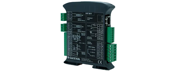

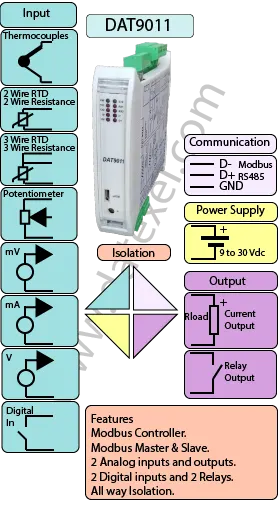
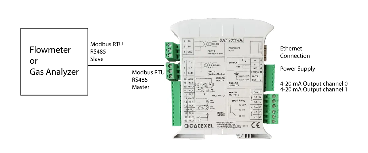
The DAT9011 Modbus RTU Master with Analog I/O is a versatile data acquisition and control unit that builds on the DAT9000 by adding on-board analog inputs and outputs. It can operate as a Modbus Master or Slave and connects over RS485 (Modbus RTU) and Ethernet (Modbus TCP) for easy integration with PLC/SCADA systems.
The DAT9011 accepts a wide range of sensor inputs, including mV, Volts, mA, RTD, Resistance, Potentiometer, and Thermocouple signals, and provides two 4–20 mA analog outputs. It also includes 4 digital inputs and 2 relay outputs for alarms, interlocks, and simple control tasks.
As an intelligent controller, the DAT9011 can read/write field registers and execute logical and mathematical functions—such as linearization, scaling, averaging, and square-root extraction—to convert raw signals into engineering values and drive outputs accordingly. Configuration is performed with Datexel’s DEV9K software (free of charge), which streamlines register mapping, I/O handling, and communications setup.
| INPUT | OUTPUT | POWER SUPPLY |
|---|---|---|
| mV, Volts, RTD, Resistance, Potentiometer, mA, Thermocouples. Digital Input. | Current 4-20mA, 0-20mA. 2 Relays. | Power Supply Voltage 10-30Vdc |
| Modbus Master/Slave RS485 | Modbus TCP Ethernet 10/100T | Reverse polarity protection 60Vdc |
| Modbus TCP Ethernet 10/100T | Modbus Master/Slave RS485 | |
| CURRENT CONSUMPTION | CONFIGURATION | ISOLATION |
| Between 45 and 80 mA | PC Programmable | Between Input/Comms/Power Supply 1500Vac. |
| EMC | HOUSING | TEMPERATURE |
| For Industrial environments | Material self-extinguishing | Operating Temperature 14°F +140°F -10°C +60°C |
| Immunity EN 61000-6-2 | Dimensions W x H x T 4" x 4 3/4 " x 7/8 " | Storage Temperature -40°F +185°F-40°C +85°C |
| Emission EN 6100-6-4 | 100 x 120x x 22.5 mm | Humidity (non condensing) 0-90% |
| Weight 3 oz 90 g |
| Input | |
| Analog Input | |
| Channel 0: | mV -100 to 100mV, Volts -100mV to 10V, Current 4-20mA, 0-20mA. RTD Pt100, Pt 1000, Ni100, Ni1000. Resistance 0-2000, Ohm. Potentiometer 20-2000 Ohm. Thermocouple J,K,R,S,B,E,T, N. |
| Channel 1: | mV -100 to 100mV. Volts -100mV to 10V. Current 4-20mA, 0-20mA. |
| Digital Input | 4 Channels. |
| Threshold | 0-3 Volts OFF 10-30V On. |
| Frequency | 300 Hz Maximum. |
| Output | |
| Output Analog | |
| Channel 1 and 2 | Current 4-20mA. |
| Output Digital | 2 Relays SPDT 2 Amp at 250 V. |
| Communication: | |
| RS485: | Port 1 Modbus RTU Master, Port 0 Modbus RTU Slave. |
| Ethernet: | Ethernet 10Base-T, Modbus TCP. |
| Power Supply: | Voltage 10 - 30 Vdc. Reverse polarity protection 60 Vdc. |
| Current Consumption: | 80 mA max. |
| Temperature rating: | Operative Temperature -4°F +140°F -20°C +60°C Storage Temperature -40°F +185°F -40°C +85°C. |
| Humidity: | (none condensing) 0-90%. |
| Housing: | Material self-extinguishing. |
| Dimensions: | W x L x H 4 x 4 3/4 x 1inch, 100 x 120 x 22.5mm. |
| Weight: | 7 oz 200 g. |
| EMC. | For industrial environments. |
| Immunity: | EN 61000-6-2. |
| Emission: | EN 61000-6-4. |
| Isolation: | 1500Vac, 50Hz, 1 Minute. |
| Configuration: | PC Configurable, DIP Switches. |
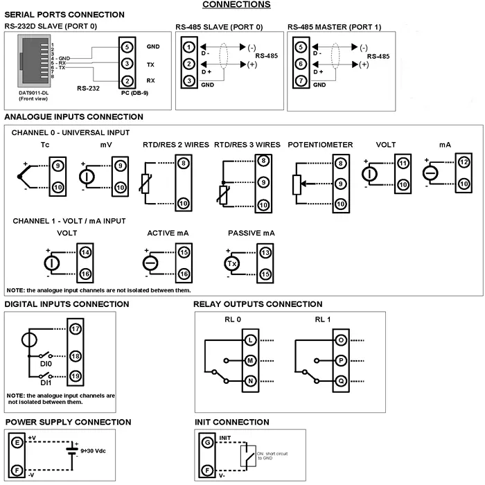
| Input. | Channel 0 | Channel 1 |
| Analog | ||
| Thermocouple | Positive 9 Negative 10 | N/A |
| mV | Positive 9 Negative 10 | N/A |
| RTD and Resistance 2 Wire | 8 and 10 | N/A |
| RTD 3 Wire | 8 and 10 Compensation 9 | N/A |
| Potentiometer | 8 and 10 Wiper 9 | N/A |
| Volts | Positive 11 Negative 10 | Positive 14 Negative 16 |
| mA | Positive 12 Negative 10 | N/A |
| mA Active | N/A | Positive 15 Negative 16 |
| mA Passive | N/A | Positive 13 Negative 15 |
| Digital | ||
| DI0 | 17 and 18 | |
| DI1 | 17 and 19 | |
| Output Analog | ||
| Current | Positive I Negative H | Positive J Negative H |
| Output Digital | ||
| Relay | Common L, NO M, NC N. | Common O, NO P, NC Q. |
| Power Supply (18-30Vdc). | Positive E Negative F. |
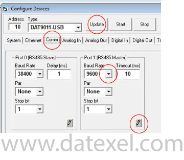
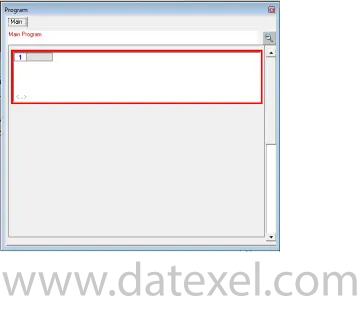
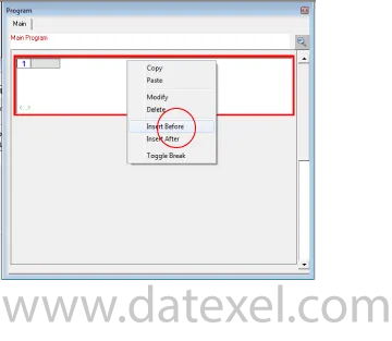
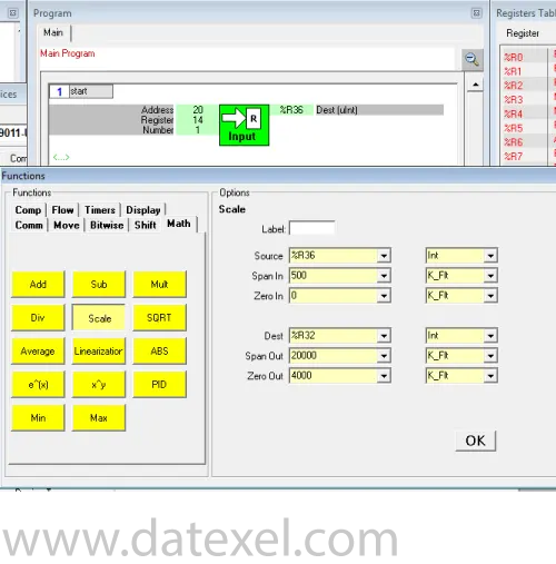
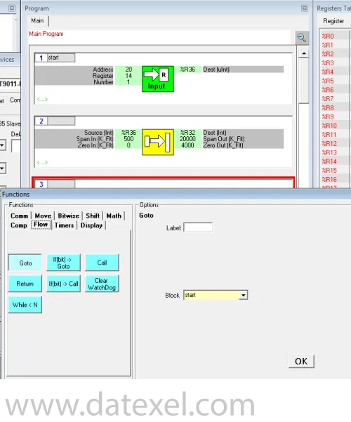
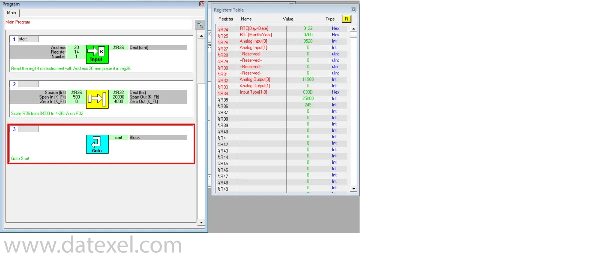
The program is made up with a group of function blocks. More information on these function blocks are available in the DAT9xxx user guide. Importantly the first function block must be labeled start and the last function block must be a goto function block with the command return to start. You can insert a function block anywhere in the program with the Insert before or after label.
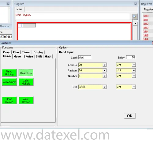
To make the program continuously run we have to insert a Goto function block.
The DAT9011 is a versatile Modbus data acquisition and control unit with on-board analog inputs/outputs and digital I/O. It can operate as a Modbus RTU/TCP Master or Slave, communicates over RS485 and Ethernet, and executes logical/mathematical functions (e.g., linearization, scaling, averaging, square-root) to convert sensor signals and drive outputs.
Inputs: mV, Volts, mA, RTD, Resistance, Potentiometer, and Thermocouple signals.
Outputs: two 4–20 mA analog outputs, plus 4 digital inputs and 2 relay outputs for alarms/interlocks and simple control tasks. Refer to the manual for specific ranges and wiring.
Configuration is done with Datexel’s free DEV9K software. You can map registers, apply scaling/linearization/averaging/square-root functions, assign inputs to the 4–20 mA outputs, and set Modbus RTU (RS485) and Modbus TCP (Ethernet) parameters.