ModBus Strain Gauge Converter
DAT3025


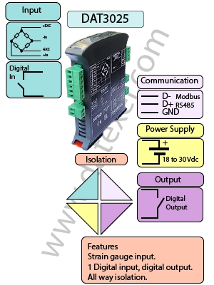
The DAT3025 Modbus Strain Gauge Converter is designed for precise acquisition of analog signals from 4- or 6-wire bridge transducers. It provides a configurable bridge excitation voltage of 5 V or 10 V, ensuring compatibility with a wide range of strain gauge transducers. Data is transmitted digitally over an RS-485 Modbus RTU/ASCII network, with an RS-232 version available on request.
The DAT3025 complies with EMC directives and is housed in a robust, self-extinguishing plastic enclosure designed for EN-50022 standard DIN rail mounting. Its slim 22.5 mm profile makes it ideal for high-density panel applications.
| INPUT | OUTPUT | POWER SUPPLY |
|---|---|---|
| +/- 30 mV. | Bridge excitation 5 V +/-10% | Power Supply Voltage 18-30Vdc |
| +/- 200 mV. | Bridge excitation 10 V +/-5% | Reverse polarity protection 60Vdc |
| Digital Tare 24Vdc. | Trip Amp SSR 48 V max | Reverse polarity protection 60Vdc |
| CURRENT CONSUMPTION | CONFIGURATION | ISOLATION |
| Between 0 mA | DAT3000-10000 soft ware | Between Input/Output/RS485/Power Supply 1500Vac. |
| EMC | HOUSING | TEMPERATURE |
| For Industrial environments | Material self-extinguishing | Operating Temperature 14°F +140°F -10°C +60°C |
| Immunity EN 61000-6-2 | Dimensions W x H x T 4" x 4 3/4" x 3/4" | Storage Temperature -40°F +185°F-40°C +85°C |
| Emission EN 6100-6-4 | 100 x 120x x 22.5 mm | UL Operative Temperature 14°F +104°F -10°C +40°C |
| Weight 3 oz 90 g |
| Input: | ||
| Input Range | Zero | Span |
| +/-200mV | -200 mV | +200 mV |
| +/-30mV | -30 mV | +30 mV |
| Bridge excitation voltage (Vexc) | R cell min | R cell max |
| 5 V +/-10% | 150 Ω | 10 ㏀ |
| 10 V +/-5% | 300 Ω | 10 ㏀ |
| Max Bridge excitation current | 50 mA | |
| Sampling Time | 200 ms | |
| Resolution | 16 bit | |
| Input Accuracy | the > of ± 0,1% f.s. | or 5uV |
| Linearity | ± 0,1% f.s. | |
| Thermal Drift | < 50 ppm/°C | |
| Warm-up Time | 3 min |
| ALARM TRIP AMPLIFIER – OUTPUT | |
| Output Type | SSR (solid state relay) |
| Output Contact | SPST |
| Max Load (resistive): | |
| Max Voltage | 48 Vdc / 30 Vac |
| Max Current | 0.4 A |
| Baud Rate | Up to 115.2 Kbps | |
| Maximum Distance | 4000 ft | 1.2 Km |
| Protocol Interface | Modbus RTU Interface RS485 | Modbus ASCII Interface RS485 |
| Option | RS232 |
| Power supply voltage | 20 .. 30 Vdc |
| Reverse polarity protection | 60 Vdc max |
| Current Consumption | 100 mA |
| Power Supply RS485 Analog input Analog output Digital Input Relays |
1500Vac 50Hz, 1 Min |
| Operative temperature | 14℉ to 140℉ |
| -10℃ to 60℃ | |
| -10℃ to 40℃ | |
| Storage temperature | -40℉ to 185℉ |
| -40℃ to 85℃ | |
| Humidity (not condensed) | 0 to 90 % |
| Maximum Altitude | 6500ft 2000m |
| Installation | Indoor |
| Category of installation | II |
| Pollution Degree | 2 |
| Weight | 6 Oz |
| 150 g. | |
| Material | Self-extinguish plastic |
| IP Rating | IP20 |
| Wiring size | AWG 14-18 |
| 0.8÷2.1 mm² | |
| Screw torque | 0.8 N m |
| Mounting | DIN rail standard EN-50022 and EN-50035 |
| Dimensions | H x" L x" T x" |
| H 100 mm L 120 mm T 22.5 mm | |
| EMC | For industrial environments |
| Immunity | EN 61000-6-2 |
| Emission | EN 61000-6-4 |
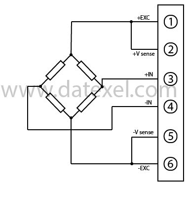
| Input. | ||
| Terminal 1 | +Excitation | |
| Terminal 2 | +Vsense | Connect to Terminal 5 |
| Terminal 3 | +IN | |
| Terminal 4 | -IN | |
| Terminal 5 | -Vsense | Connect to Terminal 6 |
| Terminal 6 | -Excitation |
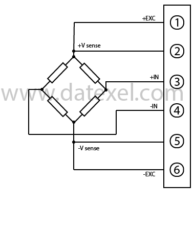
| Input. | ||
| Terminal 1 | +Excitation | |
| Terminal 2 | +Vsense | |
| Terminal 3 | +IN | |
| Terminal 4 | -IN | |
| Terminal 5 | -Vsense | |
| Terminal 6 | -Excitation |

| Input | |
| Terminal 7 | Terminal 8 |
| Output SSR | |
| Terminal K | Terminal L |
Input Voltage Off 0-3 V. On Status 10-30 V.
Output Solid State Relay.
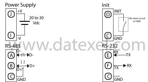
| Power Supply | ||
| 20 -30 Vdc | Terminal J Positive | Terminal I Ground |
| Init | ||
| Terminal D Init | Terminal C Ground | |
| RS-485 | ||
| Terminal A D- | Terminal B D+ | Terminal C Ground |
| RS-232 | ||
| Terminal E Tx | Terminal F RX | Terminal C Ground |

| LED | Color | State | Description |
| PWR | Green | On OFF Blink |
Power On Power Off Watch-Dog Alarm |
| STS | Yellow | Off | Correct operation |
| RX | Red | Blink Off |
Receiving Data No Data Receiving |
| TX | Red | Blink Off |
Send Data Not Send Data |
| DI | Red | On Off |
Digital Input On Digital Input Off |
| DO | Red | On Off |
Digital Output On Digital Output Off |
The ModBus Strain Gauge Converter is suitable for fitting on to an EN-50022 top hat DIN rail in the vertical position. For optimum operation follow these instructions: Install the DAT3025 side by side. However, it may be necessary to separate them by at least 5 mm in the following case: Avoid temperature exceeding 45°C. Make sure that sufficient air flow is provided for the DAT3025 ventilation slits. Avoid mounting above appliances generating heat. Fit the DAT3025 in the lower part of the panel. Avoid high vibration. Don't route conductors near power signal cables such as motors, induction ovens, inverters, also use shielded cable for connecting signals.