RTD to Modbus, Potentiometer, Resistance to Modbus converter
DAT3014 RS485


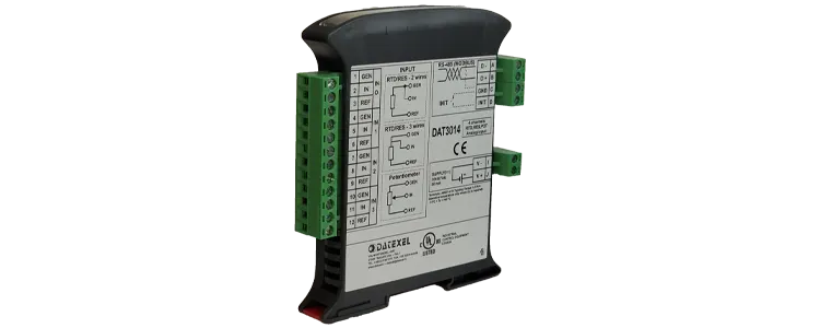
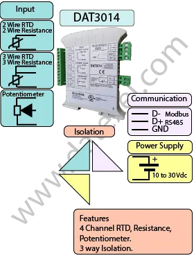
The DAT3014 Modbus Converter is a 4-channel input module designed for RTDs, potentiometers, and resistance sensors. It converts analog signals into a 16-bit digital format and transmits the data over an RS-485 network using the Modbus RTU protocol.
Supported sensor types include Pt100, Pt1000, Ni100, Ni1000, as well as resistance ranges of 0–500 Ω and 0–2000 Ω. This flexibility makes the DAT3014 suitable for a wide range of industrial temperature and resistance measurement applications.
The device ensures accurate, stable measurements and is available in an RS-485 Modbus RTU format, making it easy to integrate into PLCs, SCADA systems, and other Modbus master devices.
| Input | Output | POWER SUPPLY |
|---|---|---|
| RTD, Resistance, Potentiometer. | RS485 | Power Supply Voltage 10-30Vdc |
| Reverse polarity protection 60Vdc | ||
| Current Consumption | CONFIGURATION | ISOLATION |
| Between 30 and 100 mA | PC Programmable | Between Input/Output/RS485/Power Supply 2000Vac. |
| EMC | HOUSING | TEMPERATURE |
| For Industrial environments | Material self-extinguishing | Operating Temperature 14°F +140°F -10°C +60°C |
| Immunity EN 61000-6-2 | Dimensions W x H x T 4" x 4 3/4" x 3/4" | Storage Temperature -40°F +185°F-40°C +85°C |
| Emission EN 6100-6-4 | 100 x 120x x 22.5 mm | UL Operative Temperature 14°F +104°F -10°C +40°C |
| Weight 3 oz 90 g |
| Input: | |
| RTD | 4 Channels Pt100, Pt1000, Ni100, Ni1000 |
| Resistance | 0-500 Ohm, 0-2000 Ohm. |
| Potentiometer | 500 Ohm, 2000 Ohms. |
| Communication: | |
| RS485: | Modbus RTU Slave. |
| RS485: | Modbus Slave. |
| Power Supply: | 10 - 30 Vdc. Reverse polarity protection 60 Vdc. |
| Current Consumption: | 30 mA. |
| Temperature rating: | Operative Temperature -4°F +140°F -20°C +60°C Storage Temperature -40°F +185°F -40°C +85°C. |
| Humidity: | (not condensing) 0-90%. |
| Housing: | Material self-extinguishing. |
| Dimensions: | W x L x H 3 3/4X 3 1/2 X 1 7/8 inch, 90 x 74 x 48mm. |
| Weight: | 7 oz 200 g. |
| EMC. | For industrial environments. |
| Immunity: | EN 61000-6-2. |
| Emission: | EN 61000-6-4. |
| Isolation: | Between Modbus Master, Slave/Power supply 1500Vac, 50Hz, 1 Minute. |
| Configuration: | PC Configurable. |
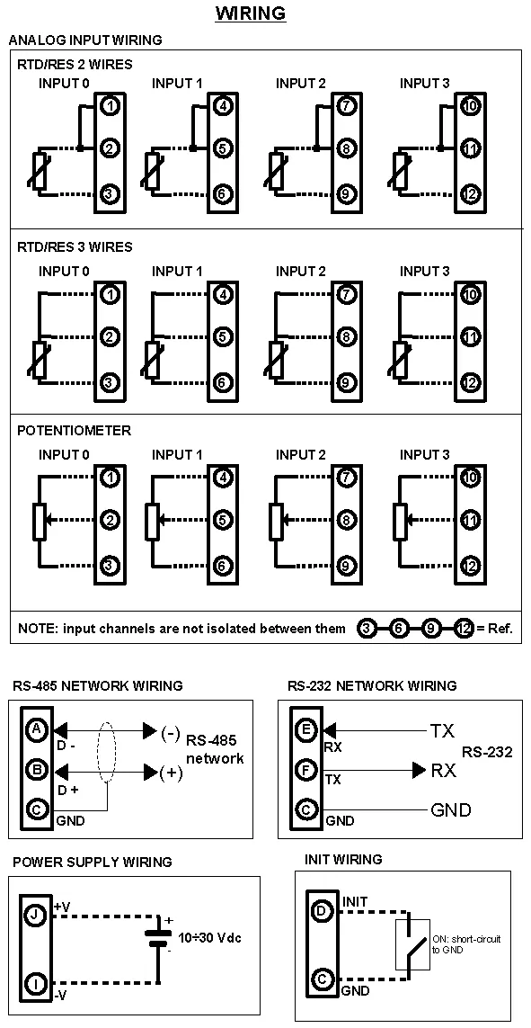
| RTD Input 0 | Sensor on 2 and 3 and Compensation on 1 |
| RTD Input 1 | Sensor on 5 and 6 and Compensation on 4 |
| RTD Input 2 | Sensor on 8 and 9 and Compensation on 7 |
| RTD Input 3 | Sensor on 11 and 12 and Compensation on 10 |
| Potentiometer Input 0 | Sensor on 1 and 3 and Wiper on 2 |
| Potentiometer Input 1 | Sensor on 4 and 6 and Wiper on 5 |
| Potentiometer Input 2 | Sensor on 7 and 9 and Wiper on 8 |
| Potentiometer Input 3 | Sensor on 10 and 12 and Wiper on 11 |
| Power Supply (18-30Vdc). | Positive J Negative I. |
| RS 485 Slave | Positive (D+)B Negative (D-) A GND C |
| RS-232D | C GND |
| E RX | |
| F TX | |
| Init | Pin D Init Gnd C |
