RTD to RS485 Modbus, Resistance to RS485 Modbus converter.

DAT3019
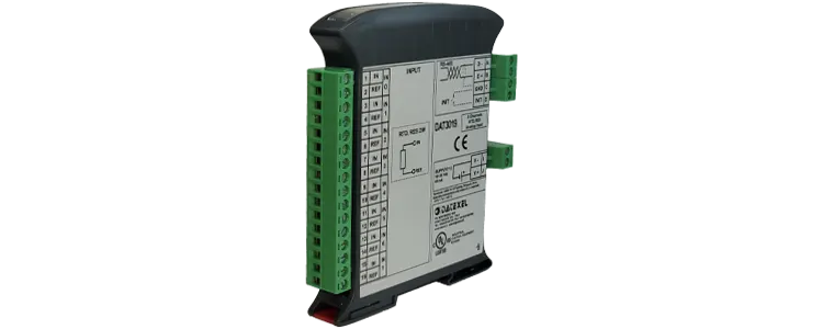
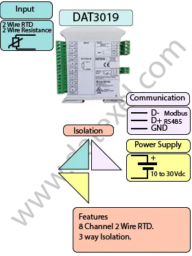
DAT3019 RTD to RS485 Modbus converter.
RTD to RS485 Modbus, Resistance to RS485 Modbus converter DAT3019.
• UL, CSA, CE.
• Modbus RTU Slave.
• RS485 Communication.
• 8 Analog Inputs RTD, Resistance.
• Isolation.
General Description

The RTD and Resistance to RS485 Modbus converter DAT3019 RS485 Modbus is an 8 Channel RTD and Resistance input RS485 Modbus converter. The DAT3019 RS485 Modbus converts the RTD and Resistance analog signal to a 16 bit digital format. The data is transmitted by the RS485 Modbus protocol on RS-485. There are several options on the RTD and Resistance input on the DAT3019 RS485 Modbus such as is Pt100, Pt1000, Ni100, Ni1000 0-500Ohms and 2000 Ohms. The DAT3019 RS485 Modbus is also available in the RS232 ASCII format.

INPUT OUTPUT POWER SUPPLY
RTD, Resistance. Modbus RS485 Power Supply Voltage 10-30Vdc
Reverse polarity protection 60Vdc
CURRENT CONSUMPTION CONFIGURATION ISOLATION
Between 30 and 100 mA PC Programmable Between Input/Comms/Power Supply 2000Vac.
EMC HOUSING TEMPERATURE
For Industrial environments Material self-extinguishing Operating Temperature 14°F +140°F -10°C +60°C
Immunity EN 61000-6-2 Dimensions W x H x T 4" x 4 3/4" x 3/4" Storage Temperature -40°F +185°F-40°C +85°C
Emission EN 6100-6-4 100 x 120x x 22.5 mm Humidity (non condensing) 0-90%
Weight 3 oz 90 g

Specifications
Input:  
RTD 8 Channels Pt100, Pt1000, Ni100, Ni1000
Resistance 0-500 Ohm, 0-2000 Ohm.
Communication:  
RS485: Modbus RTU Slave.
RS232: Modbus Slave.
Power Supply: 10 - 30 Vdc. Reverse polarity protection 60 Vdc.
Current Consumption: 30 mA.
Temperature rating: Operative Temperature -4°F +140°F -20°C +60°C Storage Temperature - 40°F +185°F - 40°C +85°C.
Humidity: (not condensing) 0-90%.
Housing: Material self-extinguishing.
Dimensions: W x L x H 3 3/4X 3 1/2 X 1 7/8 inch, 90 x 74 x 48mm.
Weight: 7 oz 200 g.
EMC. For industrial environments.
Immunity: EN 61000-6-2.
Emission: EN 61000-6-4.
Isolation: Between Modbus Master, Slave/Power supply 1500Vac, 50Hz, 1 Minute.
Configuration: PC Configurable.
Drawings

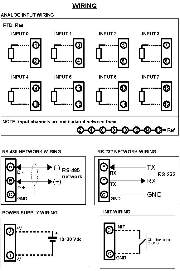
Power Supply, Inputs and INIT

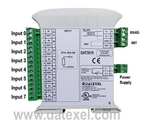
RTD and Resistance Input 0 Sensor on 1 and 2
RTD and Resistance Input 1 Sensor on 3 and 4
RTD and Resistance Input 2 Sensor on 5 and 6
RTD and Resistance Input 3 Sensor on 7 and 8
RTD and Resistance Input 4 Sensor on 9 and 10
RTD and Resistance Input 5 Sensor on 11 and 12
RTD and Resistance Input 6 Sensor on 13 and 14
RTD and Resistance Input 7 Sensor on 15 and 16
Power Supply (18-30Vdc). Positive J Negative I.
RS 485 Slave Positive (D+)B Negative (D-) A GND C
RS-232D C GND
  E RX
  F TX
Init Pin D Init Gnd C
RTD to RS485 Modbus, Resistance to RS485 Modbus converter DAT3019.

Applications
Back to General Description
Application Note Modbus RTU to measure a 2 wire RTD with a DAT3019
Printed Version

Set Up the DAT3019.

  1. Connect 24 Vdc to I and J.
  2. Connect RS485 to A and B.
  3. Connect 2 wire RTD pt100 to Input 0 on terminals 1 and 2.
  4. If the communication parameters are unknown, short out the INIT connections C and D.
  5. Power up the DAT3019 Modbus RTU Slave.
It is advisable to use the DAT3580 to connect the DAT3019 to the PC. The advantage of using the DAT3580 is that it will isolate your PC from the DAT3019. The DAT3580 options are USB, Ethernet and RS232. If the DAT3580USB version is used, install the USB drivers. If the DAT3580MBTCP or the DAT3580GW are used, make sure the Ethernet parameters are compatible with the net and transmission of data over port 502 is allowed.
DAT3019 Modbus RTU Slave for RTD's

Set Up PC.

  1. Download the 3000-10000 Software from www.datexel.com download page.
  2. Close all other software.
  3. UnZIP the Modbus_3000_10000_setup software.
  4. Run the 3000-10000 software.
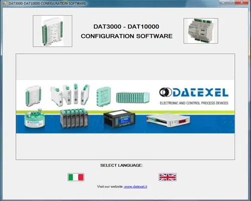
  5. To start the software click the English version.
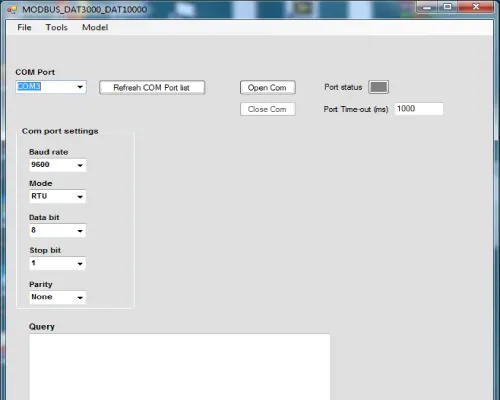
Start page for the Modbus 3000-10000 software

Set Up Communication.

  1. The software should automatically select the correct comms port. It is possible to override the comms port or refresh if you change the physical port.
  2. Choose the correct Com port settings.
  3. Click Open Com. The Port Status will change to green.
  4. The default Baud rate is either written on the Label or 38400bps. If the INIT is shorted, the Baud rate will be 9600bps, RTU, Data Bit 8, Stop Bit1, Parity None.
Communication screen for the Modbus 3000-10000 software

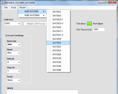
Selecting the Modbus RTU Slave DAT3019.

  1. The green light only indicates the port is open. Even if the settings are incorrect the light will turn green.
  2. Select Model and the drop down navigation will appear.
  3. Select DAT3019 for RTD or Resistance.
Selecting the DAT3019

Setting the Address of the DAT3019 Modbus Slave.

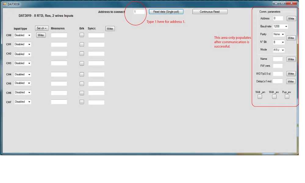
  1. Change the Address to connect to 1 or what is written on the label.
  2. Click "Read data" (Single poll).
  3. The screen should now read the temperature of the RTD Sensor once.
  4. If there is a function error, no CRC match, check Baud rate, RS485 connection or Modbus Slave Address.
  5. This needs to be fixed before further progress. If you have not used the INIT on terminals C and D, it is highly recommended that you do now. Then return to Communication set up and set the settings to 9600bps, RTU, Data Bit 8, Stop Bit1, Parity None.
  6. This will always be the correct setting unless it differs on the label.
Selecting Address 1 on the DAT3019

Feedback from Modbus Slave DAT3019.

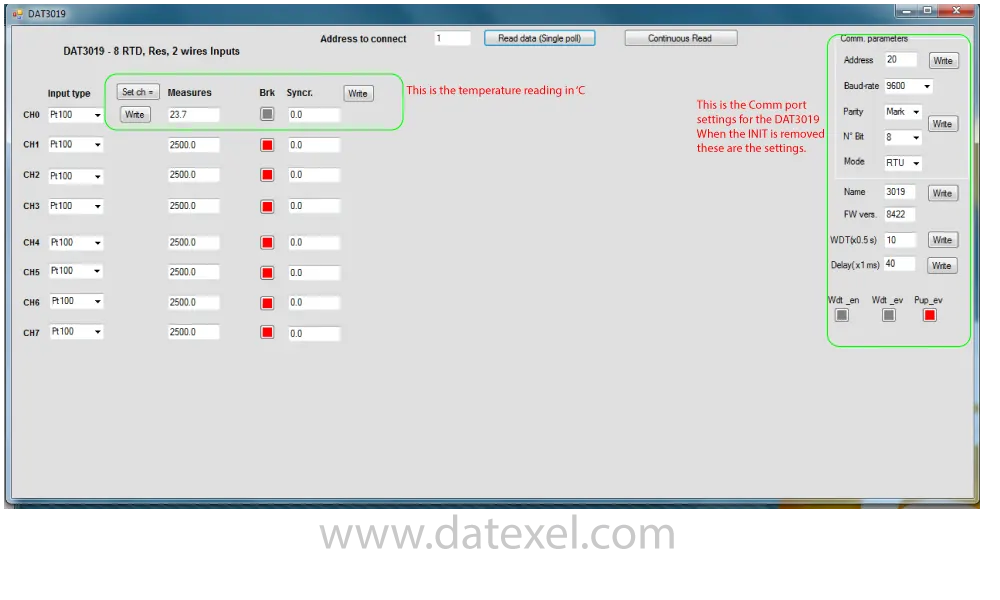
  1. If it is reading the correct temperature, you will see on the right side the default Comm parameters without the INIT link.
  2. Click "Continuous read" to see the temperature continue to update.
  3. If you need to change the Comm parameters you can write in the boxes and write to the DAT3019 Modbus RTU Slave by clicking the write button.
  4. Note, if you now remove the INIT short the DAT3019 RTD Converter will work with the new Comm parameters, not the default.
Continuing reading the temperature for the RTD on the DAT3019

Address
The actual Address of the DAT3019 connected.
Baud rate
The actual baud rate of the DAT3019 connected.
Parity
The actual parity mode of the DAT3019 connected.
N°Bit
The actual number of bit selection of the DAT3019 connected.
Mode
The actual Modbus modality (RTU or ASCII) set for the DAT3019 connected
Name
The string read from the DAT3019 of 4 ASCII characters used to name it example DAT3019.
FW Version
The firmware version read from the DAT3019.
WTD (x0.5)
The watchdog time read from the DAT3019 is in steps of 0.5 seconds.
Delay (x1 ms)
The delay time between the reception of a query and transmission of the response. Expressed as steps of 1 millisecond.
Button Wdt_en
Indicates if the bit to enable the watchdog time of the device has been set: red indicates the bit is set, grey indicates the bit is not set.
Button Wdt_ev
Indicates if the watchdog timer event is occurred: red if the event occurs, grey if the event has not occurred. This condition is also signaled by the blinking of the led “PWR” of the device and the safe state of the digital outputs.
Button Pup_ev
Indicates if the Power up event has occurred: red if the event has occurred, grey if the event has not occurred. This condition is also signaled by the power-up state of the digital outputs.