Isolated ModBus RTU 4-20mA output.
DAT10024
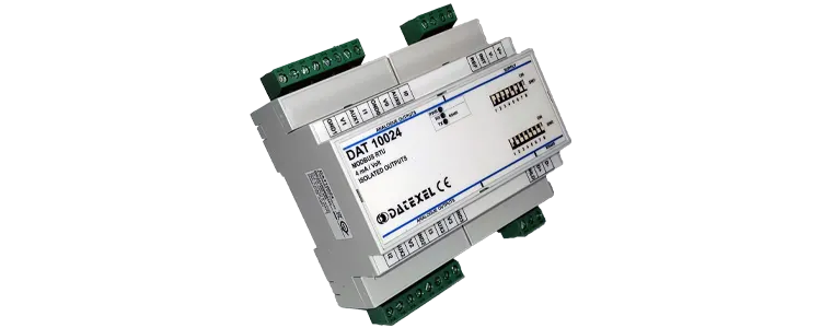

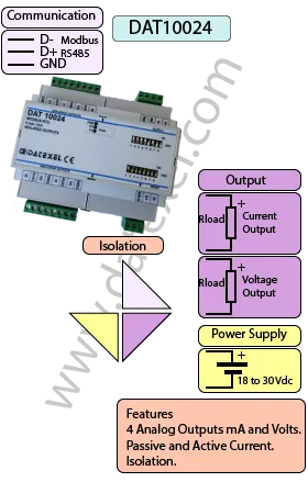
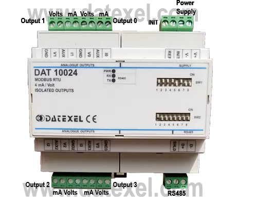
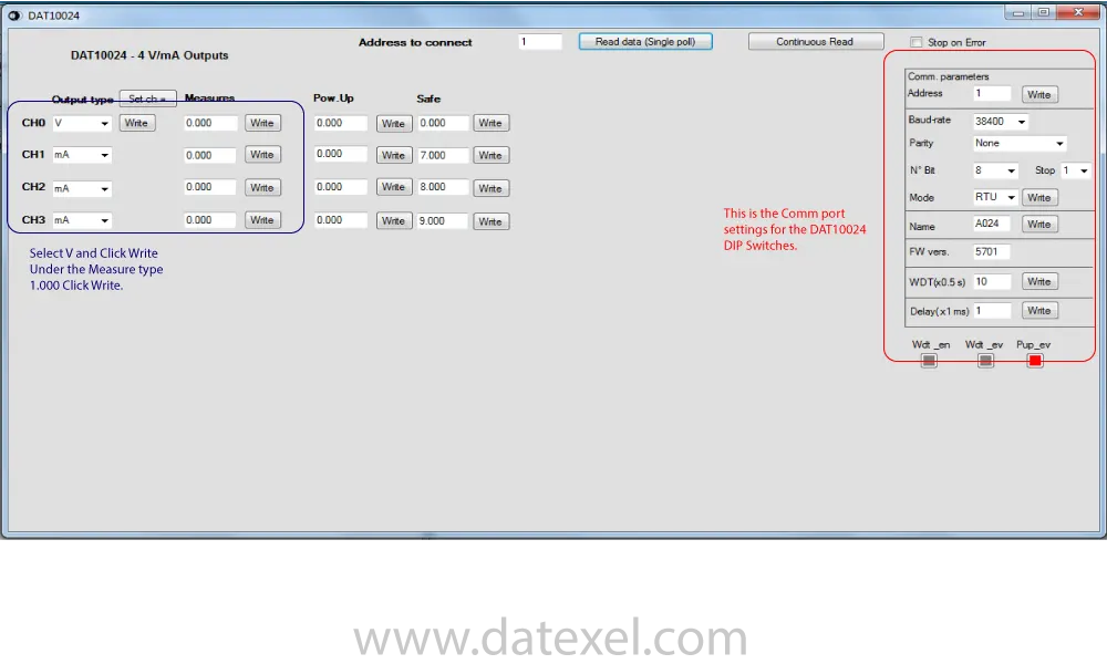
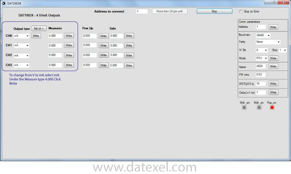
The DAT10024 Isolated ModBus RTU 4-20 mA output module is a four channel Modbus RTU Isolated Current and Voltage output converter. The DAT10024 can also operate with Modbus ASCII and has the option to select a 0-10 Vdc output. Each output channel can be set up independently i.e. Channel 0 could be 0-10 V and Channel 1 could be 4-20 mA. The power up settings can be configured differently per independent Channel. The 4-20 mA analog output can be Passive or Active. A watch dog timer is available to ensure plant safety.
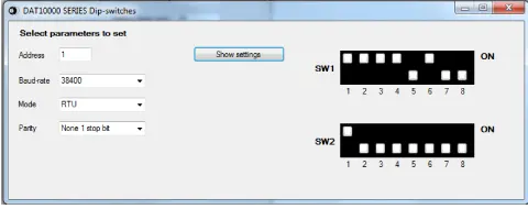
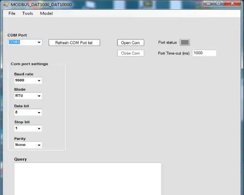
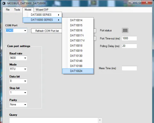
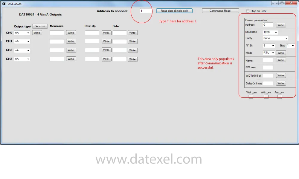
The DAT10024 is set up with either the free PC based software available on our download page or with the use of the DIP Switches. The DIP switch settings can be found in the user guide or on the 3000-10000 software as the wizard settings. The wizard settings allow you to set the switches as per the Address, Baud-rate, RTU or ASCII, and the parity.
| INPUT | OUTPUT | POWER SUPPLY |
|---|---|---|
| Modbus RTU. | 4-20mA, 0-20mA. | Power Supply Voltage 20-30Vdc |
| Modbus ASCII. | 0-10 Vdc 2-10 Vdc. | Reverse polarity protection 60Vdc |
| CURRENT CONSUMPTION | CONFIGURATION | ISOLATION |
| Between 60 and 115 mA | PC Programmable | Between Input/Comms/Power Supply 1500Vac. |
| DIP Switch Programmable | ||
| EMC | HOUSING | TEMPERATURE |
| For Industrial environments | Material self-extinguishing | Operating Temperature 14°F +140°F -10°C +60°C |
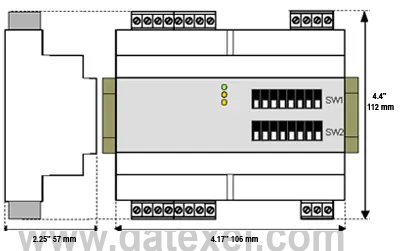
| Immunity EN 61000-6-2 | Dimensions W x H x T 4.1/4" x 4 1/2" x 2 1/4" | Storage Temperature -40°F +185°F-40°C +85°C |
| Emission EN 6100-6-4 | 106 x 112x x 57 mm | Humidity (non condensing) 0-90% |
| Weight 7 oz 200 g |
| Output type: | Min | Max |
| Current mA | 0 mA | +20 mA |
| Voltage Vdc | 0 Vdc | +10 Vdc |
| Current | ± 10 uA |
| Voltage | ± 5 mV |
| Thermal Drift | ± 0.01%/℉ |
| Load Resistance | |
| Voltage | > 5KΩ |
| Current | < 500Ω |
| Auxiliary Voltage | |
| 4 Channels | > 13 Vdc @ 20 mA |
| Response Time | |
| from 10% to 90$ | 15 ms |
| Sample Time | 50 ms |
| Data Transmission | |
| Baud rate | 2400bps to 115.2 Kbps |
| Max distance | 4000ft 1.2 Km. |
| Power supply | |
| Power supply voltage | 10 .. 32 Vdc |
| Reverse polarity protection | 60 Vdc max |
| Current Consumption | 150 mA Max |
| Isolation | |
| On all sides | 1500 Vac 50Hz, 1Min |
| Environmental Conditions | |
| Operating Temperature | -4℉ +140℉ |
| -20℃ +60℃ | |
| Storage Temperature | -40℉ +185℉ |
| -40℃ +85℃ | |
| Humidity (not condensed) | 0 to 90 % |
| Max Altitude | 2000 m |
| Installation | Indoor |
| Category of installation | II |
| Pollution Degree | 2 |
| Material | Self-extinguish plastic |
| Ingress Protection | IP20 |
| Wiring Diameter |
AWG 14-18 0.8÷2.1 mm2 |
| Tightening Torque | 0.5 N m |
| Mounting | DIN Rail EN50022 |
| Weight | 0.45 lbs. 200 g. |
| EMC | 0.45 lbs. 200 g. |
| Immunity | EN 61000-6-2 |
| Emission | EN 61000-6-4 |
| Title | With INIT | Datexel default |
| Mode | Modbus RTU | Modbus RTU |
| Baud-rate | 9600 bps | 3840 bps |
| Parity | None | None |
| Number of bit | 8 | 8 |
| Stop Bit | 1 | 1 |
| Address | 1 | 1 |
| LED | Color | State | Description |
| PWR | Green | On | Device Powered |
| PWR | Green | Off | Device not Powered |
| PWR | Green | Blink | 1 Sec Watch Dog alarm condition |
| RX | Yellow | Blink | Data on receiving line of RS485 |
| RX | Yellow | Off | No Data on receiving line of RS485 |
| TX | Yellow | Blink | Data on transmission line of RS485 |
| TX | Yellow | Off | No Data on transmission line of RS485 |
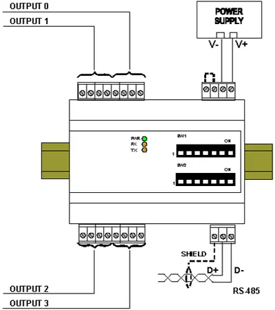
| Power Supply | |
| Positive | V+ |
| Negative | V- |
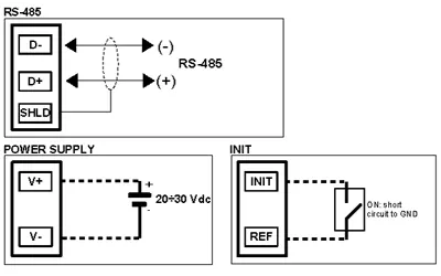
| Modbus RS485 | D- and D+ and Screen |
| INIT | INIT to REF Link |
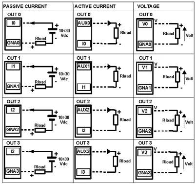
| Analog Output | |
| Channel 0 Passive Current | I0 and GNA0 |
| Channel 1 Passive Current | I1 and GNA1 |
| Channel 2 Passive Current | I2 and GNA2 |
| Channel 3 Passive Current | I3 and GNA3 |
| Channel 0 Active Current | I0 and GNA0 |
| Channel 1 Active Current | I1 and GNA1 |
| Channel 2 Active Current | I2 and GNA2 |
| Channel 3 Active Current | I3 and GNA3 |
| Channel 0 Voltage | I0 and GNA0 |
| Channel 1 Voltage | I1 and GNA1 |
| Channel 2 Voltage | I2 and GNA2 |
| Channel 3 Voltage | I3 and GNA3 |

| DAT10024 | Modbus RTU | Current |
| Column 1 Product Name | DAT10024 | |
| Column 2 Input type | Modbus RTU or ASCII | |
| Column 3 Output | Voltage or Current |
The DAT10024 comes by default with the following settings.
Address 1, RTU, Parity None, Baud Rate 38400.
The DIP Switches can be changed to your particular requirements. The options for the DIP Switch setting can be found on the Datasheet or the DAT3000-10000 software under the Wizard tab. For the above settings SW1 should have 1,2,3,4 and 6 on. SW2 Should just have 1on.
